Pages

Drilling machine types

Drilling is an operation for making drill or hole by removing metal from a workpiece by the cutting tool is called drill.
A drilling machine is made in many different types and sizes.
Each type is designated to handle a class of work or specific job to the best advantage.

Types of  Drilling Machine :

1. Portable drilling machine
2. Sensitive drilling machine
  • Bench mounting
  • Flour mounting

3. Upright drilling machine
  • Round column section 
  • Box column section

4. Radial drilling machine
  • Plain
  • Semi universal
  • Universal
5. Gang drilling machine
6. Multiple spindle drilling machine
7. Automatic drilling machine
8. Deep hole drilling machine
  • Vertical
  • Horizontal
9. Turret drilling machine

Drilling machine parts

The different parts of a drilling machine are shown in the figure below :


Drilling machine parts

  1. Base
  2. Column
  3. Table
  4. Head
  5. Spindle, quill and drill head assembly
  6. Spindle drive and feed mechanism
  • Base :
The base is the part of the machine on which vertical column is mounted.
The top of the base in the round column and has T-slots on it so large workpiece and work holding devices may be set up and bolted on it.
  • Column
The column is the vertical member of the machine which supports the table and the head containing all the driving mechanism.
The column should be sufficiently rigid so that it can up the entire cutting pressure of the drill.
  • Table :
The table is mounted on the column and is provided with T-slots for clamping the work directly on its face.
The table may be round or rectangular in shape.
For centring work below the spindle the table of drilling machine may have three types of adjustment :
  • Vertical adjustment
  • Radial adjustment
  • Circular adjustment
  • Head :
The drill head is mounted on the top of the column and houses the driving and feeding mechanism for the spindle.
In some of the machines the drill head may be adjusted up or down for accommodating different heights of work in addition to table adjustment.
  • Spindle and drill head assembly :
The spindle is a vertical shaft which holds the drill.
It receives its motion from the top shaft through bevel gears.

  • Spindle drive and feed mechanism
The spindle drive mechanism of a drilling machine incorporates and arrangement for obtaining multiple speed of the spindle similar to a lathe to suit to various conditions.
Multiple speed of the spindle may be obtained as follows : 
  • By step cone pulley drive
  • By step cone pulley drive with one or more back gears
  • By gearing

Checklist for drill press operation


  • Select material as determined by design constraints.
  • Determine the logical order of fabrication.
  • Select requirements for machine tool used in the fabrication process.
  • Determine work to be done by the drill press. 
  • Select the drill press to be used.
  • Center punch the material where it is to be drilled. 
  • Determine the method of securing the material to the drill press. 
  • Select the drill bit to be used (tapered, carbide, etc. …)
  • Secure the drill bit in the chuck, or directly in the spindle if it is a tapered bit. 
  • Determine the proper rotation speed for the conditions. 
  • Adjust the position of the v-belt to give the selected rpm. 
  • Check the setup for proper alignment and security. 
  • Ensure the bit is not touching the material. 
  • Check to ensure there is no loose-fitting clothing. 
  • Ensure safety glasses are on properly.
  • Turn on the Drill Press. 
  • Using the spindle feed handle, slowly move the bit down to drill the material. 
  • Move the handle up and down, to reduce heat and break off long strands of waste material. 
  • Use lubrication as required. 
  • Shut off drill press to check the progress of work. 
  • When complete, ensure material is not too hot, and remove material. 
  • Remove drill bit and return to storage.
  • Clean up waste from floor and drilling machine.

Drilling machine function

The main function of the drilling machine is to make drill holes in various materials with the use of a drilling tool.

The drill press is a powerful machine tool used for drilling holes in various materials.

The drill press is typically used to drill holes, but not isolated to it. With the right attachment, the drill press can countersink, mortise, sand, route designs, tap threads, ream or bore out existing holes.

For that different types of a drilling machine are available with the use of that drilling operation is done.

Feed depth of cut and machining time for lathe machine

Some important parameter keeps in mind while operating on a lathe machine.
Feed :
The feed of cutting tool in lathe work is the distance the tool advances for each revolution of the work. 
The feed is expressed in millimetres per revolution.

Depth of cut :
The depth of cut is the perpendicular distance measured from the machine surface to the uncut surface of the work piece. 
Depth of cut =  d1-d2 / 2
Where 

d1 = diameter of the work surface before machining
d2 = diameter of the machined surface

Depth of cut varies inversely as the cutting speed. 
for the general purpose, the ration of the depth of cut to the feed varies from 10:1

Machining Time :
The machining time in the lathe work can be calculated for a particular operation if the speed of the job, feed length of the job is known.
Machining time = l / s * n min
Where

l = length of the job in mm
s = feed of the job in mm 
n = r.p.m of the work 

Cutting speed of lathe machine

Cutting Speed :

The cutting speed of the lathe machine is cutting tool is the speed at which the metal is removed by the tool from the work piece.
In a lathe, it is the peripheral speed of the work past the cutting tool expressed in meters per minute.

Cutting speed = Πdn/1000 m / min

Where d = diameter of the work in mm
n = R.P.M of the work

Some example related to cutting speed : 

A steel shaft of 20 mm diameter is turned at a cutting speed of 40 m / min. Find the RPM of a shaft?


Cutting tool signature

The signature is a sequence of numbers listing the various angles, in degrees, and size of the nose radius.
This numerical method of identification has been standardized by the American Standard Association.
The seven elements that comprise the signature of a single-point cutting tool are always stated in the following order :


Cutting tool signature


Back rake angle-Side rake angle-End relief angle-Side relief angle-End cutting edge angle-Side cutting edge angle-Nose radius

7-15-6-5-4-14-3

7 - back rake angle
15 - Side rake angle
6 - End relief angle
5 - Side relief angle 
4 - End cutting edge angle
14 - Side cutting edge angle
3 - Nose radius

Lathe machine cutting tools

There are different types of cutting tool used for various operation performed on a lathe machine.
For a general purpose work, the tool used in the lathe is a single point cutting tool.
For special-purpose operations, multi-point cutting tool may be used.

Nomenclature of single point cutting tool :

Single point cutting tool nomenclature

Various single point cutting tool used for different operation it classified under the following groups.


  • According to the method of manufacturing the tool :
Forged tool
Tipped tool brazed to the carbon steel shank
Tipped tool fastened mechanically to the carbon steel shank

  • According to the method of holding the tool :
Solid tool
Tool bit inserted in the tool holder

  • According to the method of using the tool :
Turning
Chamfering
Thread cutting
Facing
Grooving
Forming
Boring
Internal thread cutting
Parting-off

  • According to the method of applying feed :
Right hand
Left hand
Round nose

All tool having a different shape and size so the main question is how to identify the right tool for that problem all tool have different cutting tool signature according to that the tool may be identified and select appropriately.

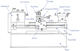
Carriage in lathe machine

Carriage

The carriage is located between the headstock and tailstock and serves the purpose of supporting, guiding and feeding the tool against the job during operation. The main parts of carriage are:

The saddle is an H-shaped casting mounted on the top of lathe ways. It provides support to cross-slide, compound rest and tool post.


The cross slide is mounted on the top of the saddle, and it provides a mounted or automatic cross-movement for the cutting tool.


The compound rest is fitted on the top of the cross slide and is used to support the tool post and the cutting tool.


The tool post is mounted on the compound rest, and it rigidly clamps the cutting tool or tool holder at the proper height relative to the work centre line.


The apron is fastened to the saddle and it houses the gears, clutches and levers required to move the carriage or cross slide. The engagement of split nut lever and the automatic feed lever at the same time is prevented she carriage along the lathe bed.
Carriage is one of the main parts of the lathe machine.

lathe machine safety precautions

While using lathe machine a safety must be needed to avoid an accident.

When we use a lathe, the following things must take great care.
  • Do not support the work piece by hand use work holding device.
  • Instead of using hand use brush to clean the chip.
  • No adjustment while the machine is operating.
  • Do not measure to attempt revolving parts.
  • Make sure that all parts are secured tightly in the lathe before starting the operation.
  • Never place tools on the drilling table.
  • Wear safety goggles and avoid loose clothing.
  • Don't keep a chuck handle attached by the chuck. Next, it flies at the moment of turning a lathe. 
  • Don't touch the byte table into the rotating chuck. Not only a byte but the table or the lathe are damaged.

Lathe machine working

How to lathe machine works? 


Lathe machine


A lathe is a machine tool which holds the work piece between two rigid and strong supports called centres or in a chuck or faceplate which revolves. 

The cutting tool is rigidly held and supported in a tool post which is fed against the revolving work. 

The normal cutting operations are performed with the cutting tool fed either parallel or at right angles to the axis of the work.

Depth of cut, feed and cutting speed and machining time is also important parameter in machining on a lathe.

When we use a lathe, the following things must take great care.

(1) Don't keep a chuck handle attached by the chuck. Next, it flies at the moment of turning a lathe.
(2) Don't touch the byte table into the rotating chuck. Not only a byte but the table or the lathe are damaged.

Operation on lathe machine

Lathe machine performs different machining operation on a lathe.

In operation the work piece may be supported and driven by anyone of the following methods :
  • Held between centres and driven by carriers and catch plates.
  • Held on a mandrel which is supported between centres and driven by carriers and catch plates.
  • Held and driven by chuck with the other end supported on the tailstock centre.
  • Held and driven by a chuck or a faceplate or and angle plate.

Operations which are performed in a lathe either by holding the workpiece between centres or by a chuck are :
  • Straight turning
  • Shoulder turning
  • Chamfering
  • Thread cutting
  • Facing
  • Knurling
  • Filling
  • Taper turning
  • Eccentric turning
  • Polishing
  • Grooving
  • Spinning
  • Spring winding
  • Forming
An operation which is performed by holding the work by a chuck or a faceplate or an angle plate is:
  • Drilling
  • Reaming
  • Borning
  • Counterboring
  • Taperboring
  • Internal thread cutting
  • Tapping
  • Undercutting
  • Parting-off
Operations which are performed by using special attachments are :
  • Grinding
  • Milling
Operation on lathe machine

Who invented lathe machine

The lathe machine Invented by
  • Henry Maudslay
Jacques de Vaucanson built the first all-metal lathe around 1751, according to Book Rags. 

Henry Maudslay, who is considered the "father of the industrial lathe," invented the first screw-cutting engine lathe in 1797.

Henry Maudslay laid an important foundation for the Industrial Revolution with his machine tool technology. 

Lathe machine types

Types of Lathe machine :

1. Speed Lathe 
  • Woodworking
  • Centring
  • Polishing
  • Spinning
2. Engine Lathe
  • Belt drive
  • Individual motor drive
  • Gear head lathe
3. Bench Lathe

4. Toolroom lathe

5. Capstan and Turret Lathe

6. Special purpose 
  • Wheel lathe
  • Gap bed lathe
  • T-lathe
7. Automatic lathe

Lathe machine function

Functions of the Lathe machine:

To remove metal from a piece of work to give it the required shape and size is the main function of the lathe.

This is accomplished by holding the work securely and rigidly on the machine and then turning it against cutting tool which will remove metal from work in the form of chips.

Lathe machine introduction

Origin to Invented :

The lathe machine is one of the oldest machine tools.

The origins of lathe can be traced back to Ancient Egypt and ancient Greece. In ancient Egypt, two-person lathes were extensively used. 
In a two-person lathe, one person would turn the wood (work piece) and the other person would cut the wood with a single-point cutting tool. Cutting operation in this lathe involved a lot of manual labour and consumed a large amount of time.

Lathe machine came into existence from the early tree lathe which was then a novel device for rotating and machining a piece of work held between two adjacent trees.


A rope wound round the work with its one end attached to a flexible branch of a tree and the other end being pulled by a man-caused the job to rotate intermittently. then had tool arrives.

With its further development, a strip of wood called Lathe. it used to support the rope and that is how the machine came to be known as Lathe.

As early as 1569, the wood lathe was used in France. after that lathe machine adapted to metal cutting in England during the industrial revolution. 

In the year 1797 Henry Maudslay, an Englishman, invented the first screw-cutting lathe which is the forerunner of the present-day high speed, heavy-duty production lathe.

Lathe machine is also known mother/father of the entire tool family.

Basic Introduction :

A lathe is a machine tool which spins a block of material to perform various operations such as cutting, sanding, knurling, drilling, or deformation with tools that are applied to the work piece to create an object which has symmetry about an axis of rotation. 

On the lathe machine, the various operation is done by the different types of cutting tool for lathe machine with the Lathe machine safety precautions

Nowadays different Lathe machine types are available all lathe have different parts   so we choose according to the purpose which Operation we have to done and then select lathe machines. All lathe machine have different functions and different working.

Nowadays automatic CNC lathe machine is invented. It makes a big impact on manufacturing industries.

Common types of the lathe are used :
  • Engine lathe 
  • Bench lathe 
  • Tracer lathe 
  • Automatic lathe
  • Turret lathe
  • Computer-controlled lathe 

Lathe machine parts and function

Description and function of lathe parts :

1. The Bed

The lathe bed forms the base of the machine. the headstock and tailstock are located at either end of the bed and the carriage rests over the lathe bed and slides over it.

The lathe bed is the main guiding member of the lathe machine so it must satisfy the following condition.
  • It should be sufficiently rigid to prevent deflection 
  • It must be massive with sufficient depth and width to absorb vibration
  • It must resist the twisting 
  • To avoid distortion
For this point of view, the bed material should have high compressive strength, should be wear-resistant and absorb vibration.

Cast iron alloyed with nickel and chromium forms a good material suitable for lathe bed.

2. The Headstock


The headstock is secured permanently on the inner ways at the left-hand end of the lathe bed.

It comprises essentially a hollow spindle and mechanism for driving and altering the spindle speed.


Lathe machine parts


3. The Tailstock


The tailstock is located on the inner ways at the right-hand end of the bed.


This has two main use: 

  • It supports the other end of the work it holds a tool for performing an operation such as drilling, reaming, tapping etc.
4. Carriage 

The carriage of a lathe has several parts that serve to support, move and control the cutting tool. 

Parts are following below :
  • Saddle
  • Cross-slide
  • Compound slide
  • Toolpost
  • Apron
Saddle is an H-shaped casting that fits over the bed and slides along with the ways. It carried the cross-slide and tool post.

The cross-slide comprises a casting, machined on the underside for attachment to the saddle and carries location on the upper face for the tool post or compound rest.

The compound rest is mounted on the top of the cross-slide. It is used for obtaining angular cuts and short tapper.

The tool post located on the top of the compound rest to hold the tool and to enable it to be adjusted to a working position.
Type of tool post :
  • Single screw tool post
  • Four-bolt tool post
  • Open side tool post
  • Four-way tool post
The apron is fastened to the saddle and hangs over the front of the bed.

Apron contains gears, clutches, and levers for operating the carriage by hand and power feeds.

5. Feed Mechanism 

The movement of the tool relative to the work is termed as "feed".

A lathe tool may have three types of feed :

  • Longitudinal
  • Cross
  • Angular
6. Gear Box

The quick-change gear-box is placed below the headstock and contains a number of different sized gears.

This is the main parts of lathe machine. according to different lathe machine types are available in the market so different types to have different parts are there for various operations on lathe machine with the safety precaution.


Factors to determine the capacity of HVAC system

What factors determine the capacity of HVAC system required :

You should know first the full forms of HVAC
  • Heating: The amount of thermal energy that needs to be added to the space.
  • Cooling: Thermal energy will sometimes need to be removed from a particular space in order to bring down the temperature.
  • Humidifying : This process says that increasing the relative humidity through the addition of water vapor into the system.
  • Dehumidifying: Process of removing water vapor from the given space.
  • Cleaning: Purifying the air by the removal of dust, smoke, pollen and other pollutants.
  • Air Movement: By this factor ensuring that there is ample movement of air to keep the inhabitants comfortable.

Turbo direct injection vs common rail

Both common rail and electronic unit injectors are better than the 12 years old technology found in the US as TDI.

Both common rail and electronic injectors are better than TDI because of much higher injection pressure. which results in better atomisation of fuel and giving more power with the lower emission.

Here are some technical difference between TDI, CRDI, and Pressurized injector.

TDI : 

TDi uses a mechanical rotary injection pump its fueling and timing controlled by a computer rather than mechanically. The rotary distributor that distributes the pressure to each injector. A metal pipe feeds the pressure to each injector which opens when the pressure is high enough to overcome a spring mechanism.

CRDI : 

A single pump which develops a high pressure feeds to each injector through a strong pipe (the rail).
The pressure in a pipe is relatively constant.
Each injector opened individually and electronically.

PI :

This type of engine feeds fuel to each injector.
Each injector is pressed by a cam lobe in the cylinder head, which pumps each injector individually and giving very high pressure.

Common rail and high-pressure unit injector are both improvements over our system.
Common rail uses a single fuel rail that is under enormous pressure. The ECU controls the injector individually.

Which one is better Technology for a Diesel Engine?

Yes the TDI is inferior to CRDI because you get more horsepower for same displacement engine size with CRDI. But emission wise, CRDI is much better. Moreover, with CRDI less fuel plumbing is required from the pump to the injectors.

Verdict :

Moving to a verdict about CRDI and TDI.
we come to know CRDI has better performance & efficiency as well due to a reason it is technologically ahead. 
But, CRDI costs more than TDI & CRDI are also bigger in size. 
On the contrary, TDI's are also good engines they offer you value for money and durability with a decent performance & efficiency as well. Moreover, TDI also needs lesser maintenance than CRDI.

Flow and Pressure

There must be a minor difference between flow and pressure. 

Water Flow :
Water Flow is a measurement of how much water is delivered at a particular outlet over a set period of time. For example, if you place a 10 litres bucket under the tap in a sink and it takes 10 seconds to fill the bucket you can see that the flow rate is 1 litre per second.

Water Pressure :
Water Pressure is a measurement of the force exerted by the water. 
We understand it by one example a cold water storage cistern in the attic may be used to supply water to a basin in a bathroom and a basin in a downstairs cloakroom. Assuming everything else is equal you will notice that the pressure at the downstairs tap is considerably more than that at the one upstairs. The increased pressure is due to the height of the cistern in relation to the tap.

Higher pressure will cause greater flow through any given pipe size, but as the flow increases, the pressure will decrease downstream due to friction loss because water velocities increase as well.

For any flow to happen, there is a requirement of pressure gradient and not the pressure. Higher the pressure gradient, keeping all other things (fluid, pipe diameter, length) constant, higher is the mass flow rate. But higher pressure does not reveal anything about the flow.


  • The pressure is defined as the force acting perpendicular to the surface of an object per unit area over which the force is distributed.
  • In the case of gases, this force is because of the collision of the gas particles with the surface. So, the pressure exerted by the gases in a given environmental condition is more of a statistical average than average value.
  • In terms of liquids, the pressure exerted is the weight of the liquid over a surface, acting on that surface.

  • The definition of flow is subjective depending on the time and length scales considered. Since we defined flow as the bulk movement of fluid particles.


If we need more water, so increase the pipe size so we don't lose more pressure to friction loss. 

PSI:
Pounds per square inch, the standard measurement of pressure in the United States.


Water Velocity:
The accepted standard for water velocity in piping systems is 5 feet per second or less. As flow increases in any given pipe size, the velocity of that water also increases. As velocity and/or flow increases in any given pipe size, the PSI loss also increases. The means of decreasing pressure loss for a given flow is to increase pipe size. (diameter)


Friction Loss:
The PSI loss which results from friction against the interior walls of pipes, directional fittings, valves or any other obstruction to the irrigation water. Once again, as flow increases so do friction loss. Friction loss is synonymous with PSI loss.


GPM, GPH, GPD:
Gallons Per Minute, the standard measure of flow; Gallons Per Hour, often used for low-volume flow such as drip irrigation; Gallons Per Day, a measure of overall water use on a daily basis.


Feet of Head:
Another term for water pressure. The pressure is directly affected by elevation change, and every 2.31 vertical feet of change upwards will decrease pressure by 1 psi in a holding tank. That is why such enormous pressures exist in the deep ocean; enough to crush a submarine as depth increases. Another way to look at it: each 1 foot elevation change equals .433 "feet of head".


Total Dynamic Head:
TDH is a measure of overall head (pressure) loss in a water system. When an irrigation designer or engineer calculates all of the friction (pressure) losses and outlet pressure required for an irrigation system, they will express the number as TDH. If an irrigation system has a maximum TDH of 250, that means that just over 108 PSI will be required to power the system.


Conversion Factors:

Pressure
To Convert From:
Into:
Multiply By:
PSI
Feet of Water
2.307
PSI
Pounds/Sq.Foot
144
PSI
Atmospheres
.06805
PSI
Bars (metric)
.06895
PSI
Inches Water @ 39.2 F
27.681
PSI
Millimeters Mercury @ 0 C
51.715
Feet of Head
PSI
.433501
Bars (metric)
PSI
14.5038
Bars
Feet of Head
33.4883
Bars
Pounds/Square Foot
2089
Bars
Atmospheres
.98692
Bars
Centimeters Mercury @ 0 C
75.0062
Bars
Inches Mercury @ 32 F
29.53


         Flow
To Convert From:
Into:
Multiply by:
GPM
Gallons/Hour
60
GPM
Cu. Feet/Second
.002228
GPM
Cu. Feet/hour
8.0208
GPM
Cu. Meters/Second (metric)
.000063
GPM
Cu. Meters/Hour
.2268
GPM
Liters/Second (metric)
.06308
GPM
Liters/Minute
3.7853
GPM
Acre-Feet/Day
.0044192
GPM
Millions Gallons/Day
694.444
Millions Gallons/Day
Acre-Feet/Day
3.0689
Millions Gallons/Day
Acre-Inches/Day
36.8266
Millions Gallons/Day
Gallons/Hour
41,666.667
Millions Gallons/Day
GPM
.00144
Liters/Minute (metric)
GPM
.26418
Liters/Minute
Gallons/Second
.004403
Liters/Minute
Cu. Feet/Second
.000588
Liters/Minute
Cu. Feet/Minute
.0353