James Nasmyth developed the metalworking shaper in 1836.
The shaper is a reciprocating type of machine intended primarily to produce a flat surface. these surfaces may be horizontal, vertical or inclined.
The shaper machine is mainly used to produce flat or plane surfaces that can be placed in a horizontal, vertical or angular plate and also used to make slots, grooves, and keyways.
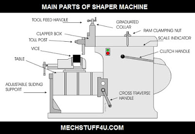
Main parts of shaper machine :
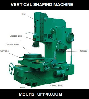
Base :
The base is the main body of the machine. It consists of all elements of the machine. The bed may be rigidly bolted to the floor of the shop or on the bench according to the size of the machine.
The base is made of cast iron to resist vibration and take up high compression load.
Column :
The Column is a box that can be attached to the base. It provides housing for the mechanism of the crank-slider and also includes the ram driving mechanism.
Two accurately guideways are provided on the top of the column on which the ram reciprocates.
Crossrail :
The cross-rail is mounted on the front vertical guideways of the column.
A horizontal crossfeed screw which is fitted within the cross-rail and parallel to the top guideways of the column.
It attaches with some cross-movement mechanism.
Saddle :
On the cross-rail, the saddle is mounted, holding the table firmly on top.
Crosswise movement of the saddle by rotating the crossfeed screw by hand or by the power to move sideways.
Clapper Box :
The Clapper box carries the tool holder.
It provides clearance for the tool in return stroke.
It also prevents the cutting edge dragging the workpiece while return stroke and prevents tool wear.
Table :
The table is bolted to the saddle from the saddle and cross-rail receives crosswise and vertical movements. It's the body of metal attached to the frame.
The main function of the table is to hold the workpiece and vice over it.
T slots for which vice and workpiece were clamped over it.
Ram :
Ram is the main part of shaper machine.
The ram is a reciprocating member of shaper machine.
Ram is in shape of semi-cylindrical and inside heavily ribbed to make it more rigid.
Ram is made by cast iron and moves over ways on the column.
It attached by the rocker arm which provide it motion in a crank driven machine and if the machine is hydraulically driven it attached by hydraulic housing.
Toolhead :
Toolhead is situated at the front of the ram.
The main function of it is to hold the cutting tool.
The cutting tool can be adjusted on it by some of the clamps.
Stroke adjuster :
It is attached below the table.
It is used to control the length of the stroke that further controls the movement of the ram.
Table supports :
These are attached front side of the table and used to support the weight of the table during working.
Working Principle:
Shaper machine works on quick return mechanism.
First of
all the workpiece is rigidly fixed on the machine table. The single point cutting tool held properly in
the tool post and it is mounted on a reciprocating ram.
A quick return motion mechanism obtains the ram's
reciprocating motion. During its forward stroke, the tool cuts the material as
the ram reciprocates.
During the return stroke, there is no cutting
action and this stroke is called the idle stroke.
One of the operating cycles of the shaper is the
forward and return strokes thus both stroke machining is done by this operation
forward and return.
The reciprocating movement of the ram and the
quick return mechanism of the machine is usually obtained by any one of the
following methods.
- Crank and slotted link mechanism
- Whitworth quick return mechanism
- Hydraulic shaper mechanism
Types of Shaper :
1. According to the type of mechanism used to give reciprocating motion to the ram :
- Crank type
- Geared type
- Hydraulic type
2. According to the travel of ram and its position :
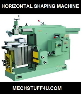
- Horizontal type
- Vertical type
- Travelling head type
3. According to the design of the table type :
- Standard shaper
- Universal shaper
4. According to the cutting stroke type :
- Push type
- Draw type
The various operations a shaper can perform are as follows :
- Machining horizontal surface
- Machining vertical surface
- Machining angular surface
- Cutting slot grooves and keyways
- Machining splines or cutting gears
- Machining irregular surface
- Dovetail slides
- Produce or combine the contour of concave/convex
Cutting speed :
The cutting speed in a shaper is the rate at which the cutting tool removes the metal.
The cutting speed of the shaper machine is given by the ratio of the Length of the cutting stroke to Time required by the cutting stroke.


