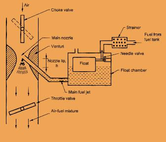
Construction and working of simple
carburettor:
Carburettors are highly complex provides an air-fuel mixture for
cruising or normal range at a single speed. Later, other mechanisms to provide
for the various special requirements like starting, idling, variable load and
speed operation and acceleration will be included. Below Figure shows that the
details of the simple carburettor.
The simple
carburettor mainly consists of a float chamber, fuel discharge nozzle and a
metering orifice, a venturi, a throttle valve and a choke. The float and a
needle valve system maintains a constant level of gasoline in the float
chamber.
If the amount of
fuel in the float chamber falls below the designed level, the float goes down,
thereby opening the fuel supply wire and admitting fuel. The float closes the
fuel supply valve thus stopping additional fuel flow from the supply system
when the design level has been reached. The float chamber is vented either to the
atmosphere or to the upstream side of the venturi.
During suction
stroke air is drawn through the venturi. Now the first question arise in your mind
that what is venturi?
It is a tube of
decreasing cross-section with a minimum area at the throat. Venturi tube is
also known as the chock tube and is shaped that it offers minimum resistance to
the airflow. The velocity increases and reaching a maximum at the venturi
throat when the air is passing through the venturi.
Correspondingly,
the pressure decreases and reaches a minimum. From the float chamber, the fuel
is fed to a discharge jet, the tip of which is located in the throat of
venturi. Fuel is discharged into the airstream because of differential
pressure known as carburettor depression. The fuel discharge is affected by
the size of the discharge jet and it is used to give the required air-fuel ratio.
As the throttle is fully opened the pressure lies between 4 to 5 cm of HG,
below atmospheric and sometimes exceeds 8 cm Hg below atmospheric.
To avoid overflow
of fuel through the jet, the level of liquid in the float chamber is maintained
at a level slightly below the tip of the discharge jet. It is also known as the tip
of the nozzle. The difference in the height between the top of the nozzle and
the float chamber level is marked as h.
The gasoline engine
is quantity governed, which means that when the power output is to be varied at a
particular speed, the amount of charge delivered to the cylinder is varied.
This is achieved by means of a throttle valve. All the parts and its functions are described below.

A carburettor consists of the
following main parts :
- Fuel strainer
- Float chamber
- Main fuel metering and idling nozzles
- Chock and throttle
Parts that mentioned above are
discussed briefly below :
- The fuel strainer :
As petrol has to pass through a
narrow nozzle exit there is every possibility that the nozzle may get clogged
prolonged operation of the engine. To prevent this possibility of blockage of
the nozzle by dust particles, the petrol is filtered by installing a fuel the strainer at the inlet of the float chamber.
The strainer made of a fine wire
mesh or other types of filtering device. The fuel strainer is either cone-shaped
or cylindrical shape.
- The float chamber :
The float chamber is to supply the
fuel to the nozzle at a constant pressure head. This is possible by maintaining
a constant level of fuel in the float bowl. The float in a carburettor is provided to control the level of fuel in the float chamber. In order to provide
the correct amount of fuel and to prevent the leakage of fuel from the nozzle
fuel level must be maintained slightly below the discharge nozzle outlet
holes.
- The main fuel metering and idling system :
The main fuel metering system of the
carburettor controls the fuel feed for cruising and the full-throttle
operations.
It consists of three principles:
- The fuel metering orifice through which fuel is drawn
from the float chamber.
- The main discharge nozzle.
- The passage leading to the idling system.
The main three functions of the main metering system is:
- To proportion the air-fuel mixture.
- To decrease the pressure at the discharge nozzle exit.
- To limit the airflow at full throttle.
- Chock and throttle :
When the vehicle is kept stationary for
a long period during cold weather, it may be overnight too then starting of
vehicle becomes more difficult.
For a low intake temperatures and
cranking speed a very rich mixture is required to initiate the combustion. The
main reason is that a very large fraction of fuel may remain as liquid suspended
in the air even in the cylinder. The most popular method of providing such mixture
is by the use of chock valve.
Throttle valve controlled the speed
and the output of an engine. The more the throttle is closed the greater is the
obstruction to the flow of the mixture placed in the passage and the less is
the quantity of mixture delivered to the cylinders.
As the throttle is opened, the
output of the engine increases. But this is not always the case as the load on
the engine is also a factor.
As we discuss the throttle is simply
a means to regulate the output of the engine by varying the quantity of charge
going into the cylinder.
Drawback of simple
carburettor:
- A fundamental drawback is providing the required A/F
ratio only at one throttle position.
- While at the other throttle positions the mixture is either leaner or richer depending on whether the throttle is opened less or more.