Involute tooth profile

What is involute?

The locus of the point on a straight line which rolls without slipping on the circumference of a circle is called the involute.

In other words, it is the path traced out by the end of a piece of the taut cord being unwound from the circumference of a circle. The circle on which the straight line rolls or from which the cord is unwound is known as the base circle.

Formation of involute tooth :


Involute tooth profile

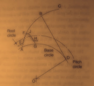
From the above figure, an involute generated by a line rolling over the circumference of a base circle with centre at O. At the start, the tracing point is at A. As, the line rolls on the circumference of the circle, the path ABC traced out by the point A is the involute. 

D can be regarded as the instantaneous centre of rotation of B, the motion of B is perpendicular to BD. Since BD is tangent to the base circle, the normal to the involute is a tangent to the base circle.  

A short length EF of the involute drawn from A can be utilized to make the profile of an involute tooth. The other side HJ of the tooth has been taken from the involute drawn from G in the reverse direction. The profile of an involute tooth is made up of a single curve, and teeth, usually, are termed as single curve teeth. 

Notes :

Because of ease of standardization and manufacture, and low cost of production, the use of involute teeth has become universal by entirely superseding the cycloidal shape. Only one cutter or tool is necessary to manufacture a complete set of interchangeable gears. The cutter is in the form of a rack as all gears will gear with their corresponding rack. The cutters of this form can be made to a higher degree of accuracy as the teeth of an involute rack are straight. 

Key points :
  • Points of contact lie on the line of action which is the common tangent to the two base circles. 
  • The contact is made when the tip of a tooth of the driven wheel touches the flank of a tooth of the driving wheel and the contact is broken when the tip of the driving wheel touches the flank of the driven wheel. 
  • If the direction of angular movement of the wheels is reversed, the points of contact will lie on the other common tangent to the base circles. 
  • Initial contact occurs where the addendum circle of the driven wheel intersects the line of action. 
  • Final contact occurs at a point where the addendum circle of the driver intersects the line of action. 
  • For a pair of involute gears, the velocity ratio is inversely proportional to the pitch circle diameters as well as base circle diameters. 
Cycloidal tooth profile

What is cycloid?

The cycloid is defined as the locus of a point on the circumference of a circle that rolls without slipping on a fixed straight line.
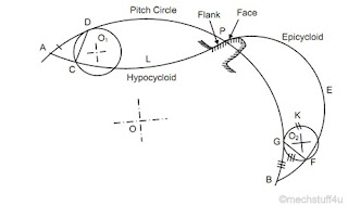
In this type, the faces of the teeth are epicycloids and the flanks are the hypocycloids. 

Now one question arises in your mind that what is epicycloids and hypocycloids? Let we check 

What is epicycloid?
An epicycloid is the locus of a point on the circumference of a circle that rolls without slipping on the circumference of another circle. 

What is hypocycloid?
A hypocycloid is the locus of a point on the circumference of a circle that rolls without slipping inside the circumference of another circle. 

Formation of cycloidal tooth :


cycloidal tooth


A circle O1 rolls inside another circle APB is called pitch circle. At the start, the point of contact of the two circles is at A. As the circle O1 rolls inside the pitch circle, the locus of the point A on the circle O1 traces the path ALP which is called hypocycloid. A small portion of this curve near the pith circle is used for the flank of the tooth.  

The line joining the generating point A with the point of contact of the two circles is normal to the hypocycloid when the circle O1 touches the pitch circle at D, the point A is at C and CD is normal to the hypocycloid ALP. 

In the same way, if the circle O2 rolls outside the pitch circle, starting from P, an epicycloid PFB is obtained.

A small portion of the curve near the pitch circle is used for the face of the tooth also. 

Some key points :
  • The path of approach is equal to the arc of approach. 
  • The path of contact is equal to the arc of contact. 
  • In case of cycloidal teeth, the pressure angle varies from the maximum at the beginning of the engagement to zero when the point of contact coincides with pitch point and then again increased to a maximum in the reverse direction. 
  • Since cycloidal teeth are made up of the two curves, it is very difficult to produce accurate profiles. This has rendered this system obsolete. 

Forms of tooth

Types of tooth :

Two curves of any shape that fulfil the law of gearing can be used as the profiles of teeth. 

In other words, an arbitrary shape of one of the mating teeth can be taken and applying the law of gearing the shape of the other can be determined. Such gear is said to have conjugate teeth. 

However, it will be very difficult to manufacture such gears and the cost will be high. It will be very difficult to replace them with the available gears. Thus, arises the need to standardize gear tooth. 

Common forms of teeth that also satisfy the law of gearing are the following :
  • Cycloidal tooth profile
  • Involute tooth profile  

Contact ratio of gears

Arc of contact :

The distance travelled by a point on either pitch circle of the two wheels during the period of contact of a pair of teeth is called the arc of contact. 

It is the length of the pitch circle traversed by a point on it during the mating of a pair of teeth. 

Thus, all teeth laying in between the arc of contact will be meshing with the teeth on the other wheel. 

Number of teeth in contact n = Arc of contact / Circular pitch 

As we mentioned above the ratio of the arc of contact to the circular pitch is also the contact ratio, the number of teeth is also expressed in terms of contact ratio. 

For continuous transmission of motion, at least one tooth of one wheel must be in contact with another tooth of the second wheel. Therefore, n must be greater than unity.

If n lies between 1 and 2, the number of teeth in contact at any time will not be less than one and never more than two. 

If n is between 2 and 3, it is never less than pairs of teeth and not more than three pairs, and so on. 

If n is 1.6, one pair of teeth are always in contact whereas two pairs of teeth are in contact for 60% of the time. 

Introduction of gears

Gears are used to transmit motion from one shaft to another or between a shaft and a slide. This is done by successively engaging the teeth. 

Gears use no intermediate link or connector and transmit the motion by direct contact. 

The two bodies have either a rolling or sliding motion. Motion is along with the tangent at the point of contact. No motion is possible along the common normal as that will either break the contact or one body will tend to penetrate into the other.  

To transmit a definite motion of one disc to the other or to prevent slip between the surfaces, projections and recesses on the two-disc can be made which can mesh with each other. This leads to the formation of teeth on the discs and the motion between the surfaces changes from rolling to sliding. The discs with teeth are known as gears or gear wheels. 

Final year project ideas for mechanical engineering

What is a project?

An individual or collaborative enterprise that is carefully planned to achieve a particular aim is called project.

Final year project is more important for students so let we discuss here how to do a good project easily for mechanical engineering students and get a good grade.

My point of view :

When you select the project title or project work for final year students you don't have sufficient time for project particularity. You will find time for that from your academic study. so I will give the advice to select easy and some creative project that will make more impact and completed in time. 
The second thing is that there are many choices for a final year project. It has mainly two category project one is purely based upon research and the second one is to make any small working model. For my point of view all students first think about to make a model but at last very few ends with clearly working model. I don't ask to choose that one but if you choose about the model you will work smart and a little bit of effort will also take. In the case of a research-based project, you have to research on a particular side like upon any material or corrosion-related research for that your work is mainly based on pen paper. You will check the research paper then make literature and then some testing upon that particular research material or component. 

Now we will see some project title that will make a good idea about selecting your project :

Model projects :

Example :
  • Auto turning fuel valve
  • Anti-theft wheel locking system  
  • Solar power air conditioning 
Above some example, you can select any model making project according to your project guide. It seems easy to difficult whatever you want to select. 

Research Projects :

Example :
  • Corrosion behaviours of material and prevention
  • Pollution related research 
Like we mentioned above you can select any research topic and make a good project with minimum effort. 

Involute gear Vs Cycloidal gear

The involute tooth profile is generally used almost everywhere and given preference over cycloidal tooth profile. First, you should know what is involute and cycloidal gear tooth profile?

What is involute gear? 

All the gear teeth have a top flat portion and two side curves. The side curves for the involute gears are in the form of the involute curve of the circle. 

It can be generated by the locus of an endpoint of an imaginary taut string unwinding from the circle.

What is cycloidal gear?

The cycloidal is a curve generated by a locus of any point on a circle which is rolling around another circle gears whose teeth profile is made of cycloidal curves is called cycloidal gears. 

The produced curve is called epicycloid if the second circle rolls outside the first circle. 

The produced curve is called hypocycloid If the second circle rolls inside the first circle.

Let us have a deep insight into the difference between involute and cycloidal gear. 

Involute gear :

  • Pressure angle remains constant throughout the operation this leads to smooth-running operation of the gears. 
  • It involves a single curve for the teeth resulting in simplicity of manufacturing.
  • Teeth have radial flanks thus are weaker. 
  • It is simple to manufacture due to the convex surface and thus are cheaper. 
  • The velocity ratio is not affected by a little variation in the centre distance.
  • Interference takes place.
  • Due to two convex surfaces are in contact, more wear and tear takes place.
  • Line of action is straight. 
  • Suitable for motion as well as power transmission. 

Cycloidal gear :

  • Pressure angle keeps on changing varies from a maximum at the beginning, reduced to zero at the pitch point and again increases to maximum this result leads to less smooth-running operation of the gears.
  • It involves a double curve for the teeth resulting in the complication in manufacturing.
  • Teeth have spreading flanks thus are stronger.
  • It is difficult to manufacture due to the requirement of hypocycloid and epicycloid and thus are costlier. 
  • To transmit a constant velocity ratio, an exact centre distance is needed.
  • There is no interference.
  • Due to concave surfaces are in contact, less wear and tear takes place.
  • Line of action is curve. 
  • Suitable for motion transmission only. 

What is rope drive

The rope drive is widely used where a large amount of power is to be transmitted. For power transmission by rope, grooved pulleys are used. 

The rope drives use the following two types of ropes :

  • Fibre ropes 
  • Wire ropes 
The rope is gripped on its sides as it bends down in the groove reducing the chances of slipping. Pulleys with several grooves can also be employed to increase the capacity of power transmission. 

These may be connected in the two ways following below :
  • Using a continuous rope passing from one pulley to the other and back again to the same pulley in the next groove, and so on. 
  • Using one rope for each pair of grooves.
Number of rope required = Total power transmitted / Power transmitted per rope 

Rope drives are, usually, preferred for long centre distances between the shafts.
Rope drive are cheaper as compared to belt drive.

Difference between heat exchanger and condenser

A condenser is a device which converts vapour into the liquid state whereas a heat exchanger is a device which is used for heat recovery also to transfer heat from two fluids.

Let us have a deep insight into the difference between the heat exchanger and condenser.

Difference : 
  • Heat exchanger only heat is transferred without phase change and heat is transferred along with the phase change in the condenser. 
  • A heat exchanger is one that extracts heat from one liquid and gives that heat to another liquid which is enclosed whereas condenser is also a heat exchanger in which phase transfer occurs for hot liquid while maintaining the same temperature and at the same time the cold liquid gets heated up. 

What does HVAC stand for

Full form of HVAC is Heating Ventilation and Air Conditioning.

HVAC can stand for a climate-control mechanism for providing thermal comfort and acceptable indoor air quality and regulate the humidity and temperature in a living environment.

It is a sub-discipline of mechanical engineering, based on the principles of thermodynamics, fluid mechanics, heat transfer and sometimes refrigeration and air conditioning. 

This technology is used for indoor and vehicular environmental comfort. Its goal is to provide thermal comfort and acceptable indoor air quality.

There are three types of setting done in HVAC :

Full Heat Setting :


Maximum airflow is directed through the heater core by the blend door to deliver the most heat possible to the main upper vents. 
So in this setting operator has demanded full heat.

Economy Mode Setting :

Maximum airflow is directed around the heater core to allow filtered air at ambient temperature to enter the cabin through the main upper vents. 

Max A/C Setting :

In this setting, the HVAC system takes air from the cabin that has already been cooled once and cools it again instead of trying to cool hot ambient air.
To get the most cooling power in this setting the operator has selected max A/C.


What is slotting machine

The slotting machine was developed by Brunel in the year 1800 much earlier than a shaper was invented. It falls under the category of the reciprocating type of machine tool similar to a shaper or a planer. Both are operated almost on the same principle but the major difference between them is in a slotter the ram holding the tool reciprocates in a vertical axis, whereas in a shaper the ram holding the tool reciprocates in horizontal axes. 

What is slotting machine?

Slotting machine is vertically reciprocating machine tool used for making a mortise or shaping the sides of an aperture, in which ram holding the tool reciprocates in a vertical axis and the cutting action of the tool is only during the return downward stoke.

The slotting machine is used for cutting grooves, keyways and slots of :


  • Various shapes
  • For making regular and irregular surfaces both internal and external. 
It is also used for handling large and awkward workpieces, for cutting internal and external gears and many other operations which can't be conventionally machined in any other machine tools.

Types of slotter machine :

There are mainly two types of slotter machine :
  • Puncher slotter
  • Precision slotter 
Puncher slotter :

It is heavy, a rigid machine designed for removal of a large amount of metal from large forging or casting. 

The length of puncher slotter is large it may be as long as 1800 to 2000 mm. 

In this machine puncher slotter, ram is usually driven by a spiral pinion meshing with the rack teeth cut on the underside of ram. The pinion is driven by a variable speed reversible electric motor similar to that of a planer. 

In this machine, feed is also controlled by electrical gear. 

Precision slotter :

It is a lighter machine and is operated at high speeds.

This machine is designed to take light cuts giving an accurate finish. 

By using special jigs, the machine can handle a number of identical works on a production basis. 

This machine is also used for general-purpose work and is usually fitted with a whitworth quick return mechanism. 

Parts of slotter machine :


  • Base 
  • Column 
  • Saddle 
  • Cross-slide 
  • Rotating table 
  • Ram and tool head assembly 
  • Ram drive mechanism 
  • Feed mechanism 
Now we can see parts in details :


Slotting machine
Base or bed :

The base is rigidly and it takes up all the cutting forces and entire load of the machine. 

It is the key parts of the machine that made from cast iron. 

The top of the bed is accurately finished to provide guideways on which the saddle is mounted. The guideways are perpendicular to the column face. 

Column : 

The column is the vertical member which is made up of cast iron. 

The column is assembled with the base and houses driving mechanism of the ram and feeding mechanism. 

The vertical front face of the column is accurately finished for providing ways in which the ram reciprocates up and down. 

Saddle :

The saddle is mounted upon the guideways and may be moved towards or away from the column either by power or manual control to supply longitudinal feed to the work. 

The top face of the saddle is accurately finished to provide guidance for the cross-slide. These guideways are perpendicular to the guideways on the base. 

Cross-slide : 

The cross slide is mounted upon the guideways of the saddle and may be moved parallel to the base of the column.

The movement of the slide may be controlled either by hand or power to supply crossfeed. 

The circular worktable is mounted on the top of the cross-slide.  

Handwheels :

It is provided for rotating the table for the longitudinal and cross traverse.

Rotary table : 

The rotary table is a circular table which is mounted on the top of the cross slide. 

The table may be rotated by rotating a worm which meshes with a worm gear connected to the underside of the table. 

The rotation of the table may be affected either by hand or power. 

The rotary table enables a circular or contoured surface to be generated on the work piece. 

Ram and tool head assembly : 

The run is reciprocating member of the machine mounted on the guideways of the column. 

It supports the tools at its bottom end on a tool head. 

A Slot is cut on the body of the ram for changing the position of the stock. 

In some mechanism, a special type of tool holders is provided to relieve the tool during the return stroke. 

Ram drive mechanism : 

A slotter removes metal during the downward cutting stroke. No metal removed during the upward return stroke.

The usual types of ram drive mechanisms are :

  • Whitworth quick return mechanism
  • Variable speed reversible motor drive mechanism
  • Hydraulic drive mechanism 
The operation performed on slotter machine :
  • Machining internal and external flat surfaces.
  • Internal recess of circular, semi-circular, concave and convex surfaces.
  • Machining internal and external circular surfaces.
  • Internal machining of blind holes.
  • For shaping internal and external forms or profiles.
  • Machining vertical, angular or inclined surfaces.
  • Machining irregular surface which is difficult to produce.
  • For machining dies and punches.
  • To cut slots, grooves, splines and keyways for both internal and external surfaces.
  • Machining internal and external gear teeth. 
Cutting speed :

The rate at which the metal is removed during downward cutting stroke is called cutting speed.
It is expressed in meters / minute. 

Depth of cut :

The perpendicular distance measured between the machined surface and the un-machined surface called the depth of cut.

It is expressed in mm. 

Feed :

The movement of the work per double stroke is called feed.
It is expressed in mm.

Cutting speed feed and depth of cut of slotter machine

Cutting speed :

The rate at which the metal is removed during downward cutting stroke is called cutting speed.
It is expressed in meters/minute. 

Feed :

A feed is the movement of the work per double stroke. 
It is expressed in mm.

Depth of cut :

Depth of cut is a perpendicular distance measured between the machined surface and un-machined surface also.
It is expressed in mm.