Difference between understeer and oversteer

Understeer and oversteer both terms are both related to vehicle dynamics and especially wheel alignment. They are related to the sensitivity of an automobile to its steering. In this article, we can check out what is understeer and oversteer and the difference between them. 

What are Understeer and Oversteer?

When a car steers less than what the driver commands is called understeer and oversteer is the turning of the car more than what the driver commands. These actions depend on the changes in lateral acceleration and steering angle. 

Difference between understeer and oversteer : 

  • Both of these are caused by the difference in slip angles for the front and rear wheels.
What is a slip angle?

It is basically the angle between the direction of the wheel heading or travel and the direction of the car heading or travel. 
  • Understeer means lack of grip while oversteer means the front side of the vehicle has more grip than the backside. 
  • When understeer happens, the driver will have little response from the steering wheel on the other side when oversteer happens, it makes the car spin when driving into a corner. 
  • Understeer takes place when the vehicle's front wheels begin to plough straight despite turning the steering wheel and oversteer takes place as a result of the rear end of a car being fishtailed or sliding out. 
  • Front-wheel drive cars are prone to understeer while rear-wheel cars are susceptible to oversteer. 
  • Understeer most commonly happens due to early accelerating while turning in a corner so you can lift the weight distribution that takes the control off of the front tires and leads to the dangerous situation while oversteer is not something to be concerned about because it happens in everyday driving thus it could be dangerous if occurs in snowy, muddy or rainy conditions. 
  • Applying more suspension or increasing the front wing can minimize the understeer and also tire pressure adjustment helps sometimes while you have to do the opposite to fix this problem you have to loosen the suspension or down-force to drop the grip. 

Explore more information:

Advantages and disadvantages of resistance welding

The resistance welding process is also a fusion welding process where both heat and pressure are applied to the joint but no filler metal or flux is added. The heat necessary for the melting of the joint is obtained by the heating effect of the electrical resistance of the joint and hence, the name is resistance welding. In this article, you can check out the advantages and disadvantages of resistance welding to understand more about it.


Advantages of resistance welding :

  • It is a very economical process because there are no consumables used in this process so environment-friendly too. 
  • The heating of the workpiece is confined to a very small part so less distortion.
  • Very little skill is required to operate a resistance welding machine because easily automated. 
  • By this process also weld dissimilar metal as well as metal plates of different thicknesses.
  • Welding speed is very high.
  • Weld up to 0.1 mm thin as well thick up to 20 mm metals. 
  • High production rate thus suited for mass production. 
  • This process does not require any filler metal, flux and shielding gas. 

Disadvantages of resistance welding :

  • The resistance welding machine is highly expensive.
  • Lower tensile and fatigue strength.
  • It is limited only to lab joints.
  • The limit of sheet metal thickness is less than 3 mm.
  • Less efficient for high conductive materials. 
  • High electric power is required. 

Advantages and disadvantages electrochemical machining

A method of removing metal by an electrochemical process is called electrochemical machining in short ECM. This process is usually used for mass production and working with extremely hard materials that are difficult to machine using other processes but its use is limited to electrically conductive materials. Let us have a deep insight into the advantages and disadvantages of electrochemical machining in this article. 

Advantages of Electrochemical Machining :

  • The metal removal rate is quite high for high-strength-temperature-resistant (HSTR) materials as compared to the conventional process.
  • Accurate machining.
  • Residual stress is low.
  • The surface finish is in the order of 0.2 to 0.8 microns.
  • No direct contact between tool and workpiece.
  • Negligible wear and tear of tool material.
  • Environmental friendly.
  • Possible to machine non-rigid and open workpieces.
  • It can be a machine configuration that is beyond the capability of the conventional machining process.
  • Extremely thin sheets of metal can be worked easily without distortion.
  • A job with complex shapes can be machined easily and accurately.
  • Several holes can be done at once during drilling.
  • ECM is a time-saving machining process as compared to conventional machining.
  • Deburring can be done in hard to access areas.
  • Fragile and brittle materials can be machined easily by ECM without cracking or breaking.
  • The metallic workpiece is not damaged due to thermal stresses.

Disadvantages of Electrochemical Machining :

  • Power consumption is more.
  • Initial tooling can be timely and costly.
  • Non-conducting materials can not be machined.
  • The process is costly because of expensive equipment.
  • A continuous supply of electrolytes is necessary.
  • Steady voltage should be maintained during the whole process.
  • Corrosion and rust of the ECM machine can be a hazard.
  • If hydrogen is liberated at the tool surface then it is possible to suffer from hydrogen-embitterment of the surface.
  • There may be a possibility of damages because of sparks.
  • Conventional machining produced more improved fatigue properties than ECM.

Advantages and disadvantages of internal expanding brake

An internal expanding brake consists of two shoes where the outer surface of the shoe is lined with some friction material to increase the coefficient of friction and prevent wearing away of the material. This type of brake is used in cars and light trucks. Let us have a deep insight into the advantages and disadvantages of internal expanding brake in this article. 

Advantages of internal expanding brake: 

  • Requires little maintenance.
  • It has a simple construction with a small number of parts.
  • It is cheaper as compared with other types of brakes.
  • It is more reliable due to the small number of parts.
  • Offers protection against the entry of foreign particles.
  • Produce a large braking torque with a small actuating force.

Disadvantages of internal expanding brake :

  • Poor heat dissipating capacity.
  • It becomes self-locking due to wear.

Advantages and disadvantages of Stirling engine

A Stirling engine is operated by cyclic compression and expansion of air or other gas at different temperatures and convert heat energy into mechanical work thus it is also called a heat engine. Let us have a deep insight into the advantages and disadvantages of the Stirling engine to know more about it. 

Advantages of Stirling engine :

  • Stirling engines can run directly on any available heat source not produced by combustion so they can run heat from biological, geothermal, nuclear sources or solar.
  • Most Stirling engine types have the cool side of the engine bearing and seals. They only need less lubricant and last longer than other types of engines that reciprocate.
  • In some ways, the engine mechanisms are simpler than other types of engines that reciprocate.
  • No valve is needed. 
  • A Stirling engine uses a single-phase working fluid that keeps an internal pressure close to the pressure of design.
  • Low operating pressure permits the use of lightweight cylinders in some cases.
  • They can be constructed to run smoothly and without an air supply.
  • In cold weather, they start easily and run more efficiently.
  • They can extremely flexible.
  • They can be used as CHP in winter and as a cooler in summer.
  • Waste heat is easily harvested.
  • Stirling engine is useful for duel-output heat and power systems.

Disadvantages of Stirling engine :

  • Stirling engine requires heat exchangers for heat input and for heat output.
  • For efficient operation, all thermodynamic cycles require large temperature differences.
  • Dissipation of waste heat is especially complicated because coolant temperature is kept as low as possible to maximize thermal efficiency.
  • A Stirling engine cannot start instantly and literally needs to warm up. It is true for all external combustion engines but for this warm-up time may be longer.

Advantages and disadvantages of abrasive jet machining

The principle of Abrasive jet machining involves the use of a high-speed stream of abrasive particles carried by a high-pressure gas or air on the work surface through a nozzle. The metal removal occurs due to erosion caused by the abrasive particles impacting the work surface at high speed. Let us have a deep insight into the advantages and disadvantages of abrasive jet machining in this article. 

Advantages of Abrasive Jet Machining :

  • Abrasive jet machining is suitable for materials of any hardness and brittleness like ceramics, germanium, glass.
  • Ability to cut fragile and heat-sensitive materials without damage as there is no heat generated by gas or air passage.
  • Low capital cost.
  • Holes of intricate shapes could be produced efficiently.
  • It can be utilized for cutting, drilling, polishing, deburring, cleaning of the materials.

Disadvantages of Abrasive Jet Machining :

  • The material removal rate is slow. 
  • The precision of the machining is poor and the wear rate of the nozzle is high.
  • Additional cleaning of the work surface may occur because the abrasive particles may remain embedded in the work surface.
  • Abrasive particles cannot be reused.
  • A dust collection chamber is a basic requirement to avoid causing health hazards from atmospheric pollution.

Steering axis inclination | Definition | Purpose | Effect

Definition of Steering axis or Kingpin inclination : 

The inclination of the kingpin from vertical is called the king inclination or steering axis inclination. 

Steering axis inclination causes both front wheels to gain positive camber because they steer away from the centre.

In modern cars where the kingpin has been replaced by the ball joints, this term has also been termed as steering axis inclination. It is defined as the inclination of the ball joint axis from the steering vertical axis. The steering axis is an imaginary line drawn through the lower and the upper steering pivot pins. 

Steering axis inclination is set by the dimensions of the upright and therefore no adjustable once it defined. 

Purpose of steering axis inclination :

To determine vehicle stability while moving on the straight road. 


Steering axis inclination

Effect of steering axis inclination :

Kingpin inclination also called steering axis inclination helps the straight-ahead recovery, thus providing directional stability. When the vehicle takes a turn, the inclination of the kingpin causes the vehicle body to move up in relation to the wheels. So when the steering wheel is left after the turn is completed, the weight of the vehicle tends to return the wheels to the straight-ahead position. 

Amount of inclination is about 7 to 8 degrees. However, the exact amount is decided considering the wheel rack value. It is kept below 8 since too much inclination cause a lot rising of the front axle when steering. 

Wheel alignment explained | Factors | Steering geometry | Linkage

What is wheel alignment?

Wheel alignment is the positioning of the steered wheels to achieve the directional stability during straight-ahead position, perfect rolling condition on steering and recovery after completing the turn. 

Factors of wheel alignment : 


Toe in Toe out

Wheel alignment is used in connection with the stability and control of the vehicle while in the situation of motion. It means that while moving straight ahead the wheels should be parallel. In the event when they are pointing inward, they are said to toe in whereas if they are pointing outward they are said to toe out. Both these situations are undesirable because in either case while rolling forward, each wheel will be simultaneously slipping laterally due to which a continuous cross-tread scrubbing would take place. 

For good handling, steering, and vehicle stability, it is also necessary that 
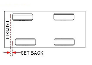
  • There should no be any setback, which is said to be the distance between the placing of the front tyres. In other word set back is a condition in which one wheel on an axle is in front of or behind the other wheel in relation to the chassis frame. When a set back of less than 6 mm is considered normal tolerance by some manufacturers. 
  • The thrust angle should be zero. Thrust angle is the angle made by the thrust line with the longitudinal centre line of the vehicle. If the thrust angle is not zero, the vehicle will dog track the steering wheel will not be centred. When the thrust angle is zero, rear wheels follow the front wheels properly. Obviously, for this condition, all the four wheels should be parallel to the frame. This is called tracking. 
Set backThrust angle


For effective steering under all conditions and at all loads, it is very important to consider and understand the factors which influence the stability and control of the vehicle. The factors are following below : 
  • Factors pertaining to wheels 
  • Steering geometry
  • Steering linkage
  • Suspension system 
Factors pertaining to wheels : 
  • Balance of wheels 
  • Inflation of tyres 
  • Brake adjustment 
Steering geometry : 
  • Camber 
  • Caster 
  • Toe-in 
  • Toe-out
Steering linkage :
  • Kingpin inclination ( Steering axis inclination )
  • Combined angle and scrub radius 
  • Over-steer 
  • Under-steer 

Requirement of good steering system

For smooth and appropriate operation and performance of the steering system vehicle should fulfil the requirement given below : 

  • The steering system should be very accurate and easy to handle. 
  • The effort required to The spear should be minimal and must be not tiresome to the driver. 
  • The steering the mechanism should also provide directional stability implies that the vehicle should have a tendency to return to its straight-ahead position after turning.
  • To provide pure rolling motion to the wheel. 
  • It should be designed in such a manner that shocks of the road are not transmitted to the driver. 

Principle of steering system

The steering system used along with suspension system allow driver to safely and easily control the direction of vehicle while driving. Now you can check the some functions of steering system. 

Primary function of steering system is to achieve accurate angular motion of the front wheels to negotiate a turn. This can be done through linkage and steering gear which convert the rotary motion of the steering wheel into angular motion of the front road wheels. 

Secondary function of steering system are following below : 

  • To provide directional stability when the vehicle running on the straight road. 
  • To provide perfect steering condition. For example perfect rolling motion of the road wheels at all times. 
  • To provide facilitate straight ahead recovery after completing a turn. 
  • To minimize tyre wear.

Advantages and disadvantages of carburetor

Carburetion is the process of formation of a combustible air-fuel mixture by mixing the proper amount of fuel with air before admission to the engine cylinder. The device with does this job is called a carburettor. Let us have a deep insight into the pros and cons of the carburettor in this article. 

Advantages of carburettor :

  • Carburettor parts are not as expensive as that of fuel injectors, especially EFI, which would give you large savings.
  • With the use of carburettor, you get more air and fuel mixture.
  • In terms of the road test, carburettors have more power and precision.
  • Carburettors are not restricted by the amount of gas pumped from the fuel tank, which means that cylinders can pull more fuel through the carburettor, leading to a denser mixture in the chamber and higher power.

Disadvantages of carburettor :

  • The mixture provided by a carburettor is so weak at very low speed that it will not ignite properly and some arrangement in the carburettor is required for its enrichment under such conditions.
  • The working of the carburettor is affected by changes in atmospheric pressure. 
  • It provides the right mixture at only one engine speed and load, therefore only suitable for engines running at a steady increase or decrease in speed.
  • More fuels are consumed since carburettors are heavier than fuel injectors.
  • More air emissions than fuel injectors.
  • Maintenance costs of the carburettor are higher than with fuel injection system.

Advantages and disadvantages of gaseous fuel

Gaseous fuels are hydrocarbons, hydrogen and carbon monoxide mixtures present in a gaseous state that form the basis of potential heat energy or light energy that can be easily disseminated through pipes from source to place of consumption. Let us have a deep insight into the pros and cons of gaseous fuel in this article. 

Advantages of Gaseous fuels :

  • They can be conveyed easily through a pipeline to the actual place of need that is the main reason for eliminating the manual labour cost in transportation.
  • They can be lighted at moment's notice.
  • They have high heat content and hence, help us in having high temperatures.
  • They can be pre-heated by the heat of hot waste gases, thereby affording the economy in heat.
  • Their combustion can readily be controlled for changes in demand like oxidizing or reducing atmosphere, length of flame etc.
  • They burn without any smoke.
  • They are ashless so there is no labour involved in ash handling.
  • They are clean in use.
  • They do not require any special burners.
  • They can be produced by using even the poorest quantity of coal.
  • They burn without heat loss, due to convection currents.
  • They burn in slight excess of air supply.
  • They are free from solid and liquid impurities.
  • Complete combustion without pollution is possible due to the uniform mixing of air and fuel.
  • They have high calorific value as well.
  • They can also be used in internal combustion engine fuels.

Disadvantages of Gaseous fuels :

  • Very large storage tank needed for them.
  • They are highly inflammable, so chances of fire hazards are high in their use.
  • They are more costly as compared with solid and liquid fuels.
Explore more information:

Drum brakes vs Disc brakes | Difference

A brake is a mechanical device that slows down a motion by absorbing energy from a moving system. Braking is done due to the friction between two surfaces. The heat generated during braking is the major problem nowadays so different brakes are used where this heating problem is resolved. 

Brakes are mainly classified into three main categories mechanical brake, hydraulic brake, pneumatic and electric brake. 

Nearly the same idea as the disk and drum brake the difference is its working. They both fall under the mechanical brake. Here, you can check it out the difference between disc and drum brake. 

What is a disc brakes?

The disk brake has a metal plate in the shape of a disk and a calliper that is attached to the wheel and the disk is rotated with the car wheel. The calliper is used on the pads for exerting power. The friction lining of the calliper comes into touch with a tiny part of the disk. The reaming part of the disk enables the surroundings to dissipate the heat. Two pads are used on either side of the disk and both pads are connected to the friction lining. Calliper is connected to the non-rotating part and on both pads it exerts force. When the brake paddle is pushed, the pads are pushed against the rotating disk as well, the friction between the disk and the pads will retard the speed of a car and prevent the disk.

What is a drum brakes?

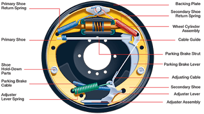
The drum brake is a small drum that rotates with the wheel and has inside a pair of shoes known as brake shoes. When the brake paddle is pressed, the brake shoes are forced against the side of the drum walls and the brake is applied by means of friction.

Drum Brakes vs Disc Brakes | Difference between the drum and disc brakes : 

  • In the case of disc brakes friction surfaces are directly exposed to the cooling air, whereas in the drum brakes, the friction occurs on the internal surfaces, from which heat can be dissipated only after it has passed by conduction through the drum. 
  • The friction pad in the case of disc brakes is flat as compared to curved friction linings in the case of drum brakes means that there is uniform wear of friction pads. Adding that the friction pad material is not subjected to any bending, thereby increasing the range of materials from which to choose the suitable one. Generally, we use asbestos fibre with metal oxide fillers bonded with organic compounds as the material for friction pads. 
  • Unlike the standard drum brake, the design of the disc brake is such that there is no loss of efficiency due to expansion. As the system becomes hot, expansion of the drum of the internally expanding shoe type of brake tends to move the friction surfaces apart, causing a loss of effective pedal travel. On the other hand, disc expansion merely changes the relative positions on the friction surfaces slightly without tensing to increase the clearance. 
  • Disc brake weighs less than their conventional drum-type counterpart, so a saving of approximately 20 to 30 % is possible. 
  • The disc brake has comparatively better anti-fade characteristics as compared with drum brakes. 
  • Drum brakes are simple in design as compared to disc brakes. There are very small numbers of parts to wear or do not function properly. 
  • When required, replacing the friction pads is very easy compared to the type of drum where the brake lining must be either riveted or attached to the brake shoes with adhesives.
  • Changes in brake factor for a unit change in friction coefficient is much less in the use of disc brakes than it is for two leading shoes or the simple, leading or trailing shoe brakes. 
  • Compared to conventional drum-type brakes, the total frictional area of pads in disk brakes is very less. The approximate ratio of 1:4 means that disc brakes have greater pressure intensity than drum brakes. 
  • Drum brakes are purely mechanically operated whereas disc brakes are mechanically operated but also be linked with ABS system and some other advanced technology. 
  • Drum brake has less torque transmitting capacity and disc brake has high torque transmitting capacity in a small volume. 
  • Disc brakes are as easy to control and have a fast response time as compared to drum brakes. 
  • The drum brake may be self-locking while the disc brake lever.
  • Drum brake maintenance is cheaper than disk brake maintenance.
The above point implies that frequent relining would be necessary, due to an increased rate of wear. So that there are compensating factors are the following below :
  1. Pads can be made considerably thicker, for a given initial cost, so that more wear can take place before replacement is necessary. 
  2. New wear-resistant friction materials that are more suitable for disk brakes than for drum brakes have been developed.

Summary : 

The only factor limiting the more extensive use of disc brakes is their initial cost. However, with further improvement in design and savings due to increased production. It is hoped that ultimately this type may replace the drum type brakes altogether at least for medium to heavy vehicles. 

Disc brakes | Construction | Features

Construction : 

A disc brake can be made of a cast-iron disc bolted to the wheel hub and a stationary housing called calliper. The calliper is connected to some stationary part of the vehicle, like the axle casing or the stub axle and is cast in two parts, each part containing a piston. 

In between each disc and the piston, there is a friction pad held in position by retaining pins, spring plates etc. Passages are drilled for the fluid in the calliper to enter or leave each housing. These passages are also connected to another passage for bleeding. Each cylinder contains a rubber sealing ring between the cylinder and the piston. 

When the brakes are applied, hydraulically actuated pistons move the friction pads into contact with the disc, and later applying equal and opposite forces. On releasing the brakes, the rubber sealing rings act as return springs and retract the friction pad and pistons away from the disc. 


Disc brake


For this type of brake, 


T  = 2 µ p a R
Where, 
µ = fluid pressure 
a = cross-sectional area of one piston 
R = distance of the longitudinal axis from the wheel axis of the piston 

For special types of disc brakes include the swinging calliper type and the sliding calliper type. 

In-swinging calliper type the calliper is hinged about a fulcrum pin and one of the friction pads is fixed to the calliper. The fluid under pressure presses against the disc to the other pad to apply the brake. The reaction the calliper causes it to move the fixed pad inward slightly, applying equal pressure to the other side of the disc. The calliper automatically adjusts its position by swinging around the pin. 

In the sliding calliper type, there are two pistons between which the fluid under pressure is sent which presses on friction pad directly onto the disc, whereas the other pad is pressed indirectly via the calliper. Both these types are adjusting and have resulted in a simpler and lighter construction. 


Features : 

The discs of the brakes have made of pearlitic grey cast iron. The material is anti-wear properties. Cast steel discs have also been employed in certain cases, which are still less and provided a higher coefficient of friction, yet the big drawback in their case is the less frictional behaviour. 

Recently material like ceramics and carbon fibre have also found their way into automotive brakes. The greatest advantage of these materials is the weight reduction which greatly improves vehicle dynamics and steering characteristics, due to the reduction in unsprung mass. 

Two types of discs have been employed in various makes of disc brakes, for example, solid or the ventilated type. The ventilated type no doubt provides better cooling. It is seen that using a ventilated disc results in a reduction of about 30% in the pad temperature, as compared to solid discs. This results in a longer pad life. Whereas the ventilated discs also have certain disadvantages. They are usually thicker and even sometimes heavier than the solid discs. 

Some disc brakes use such friction pads as contain metallic contact inside. The contact is exposed when the pad wears down to the specified thickness and thereby completes an electrical circuit which lights up a warning lamp on the instrumental panel, indicating to the driver that the pads need replacement. 

Some large pistons for disc brakes are made of hard plastic whereas in some other cases, these are precision ground and plated with nickel-chrome which provides them with a hard surface which is durable. 

Drum brakes | Construction and Types | Factors

Construction and Types : 

In this types of brakes, a brake drum is attached concentrically to the axle hub whereas on the axle casing is mounted a backplate. In case of the front axle, the brakes plate is bolted to the steering knuckle. The backplate is made of pressed steel sheet and is ribbed to increase rigidity and to provide support for the expander, anchor and the brake shoes are protects the drum and shoe assembly from dust and mud. 

However, it absorbs the complete torque reaction of the shoe due to which reason it is sometimes also called a torque plate. Both brake shoes are anchored on the backplate. Friction linings are mounted on the brake shoes. Retractor springs are used to serve to keep the brake shoes away from the drum when the brakes are not applied. The brake shoes are anchored at one end whereas on the other hand force F is applied by means of some brake actuating mechanism. Which forces the brake shoe against the revolving drum, and hence applying the brakes. An adjuster is also provided to compensate for wear of friction lining with use. 

The relative braking torque obtained at the shoes for the same force applied at the pedal varies depending upon whether the expander is fixed to the brake plate or floating If the anchor is fixed or floating and then the shoes are leading or trailing. 


Drum brakeA

  • Fixed expander type : 
To understand the action of this type it is necessary to understand the terms 'leading' and 'trailing' shoes. 

It is seen that a leading shoe tip is dragged along the drum even when there is no braking force, while the tip of the trailing shoe is thrown off the brake drum. Thus when the brakes are applied, the net force exerted on the leading shoe becomes more than the net force exerted on the trailing shoe and as such unequal braking effect is produced at the two shoes. With increased braking effect and consequently higher temperatures, the coefficient of friction gets reduced more with prolonged application in case of the leading shoe, due to which reason, leading shoe fades quicker than the trailing shoe. 


Fixed expander type drum brake


  • Floating expander type :
In this type, the expander is not fixed on the backplate but is kept floating. In this way, the unequal braking effects at the two shoes are automatically balanced and made equal. Even if the lining on one shoe is worn more than on the other, the floating expander will move to one side so that the shoes still share equally the actuating force. However, the lining wear on two shoes is still unequal. 


  • Floating anchor type :  
In this type of shoe operating mechanism, the two shoes are linked together at the floating anchor and have a common fixed anchor. For the direction of rotation, it is seen that both the shoes become leading, the details including merits and demerits of which are given below under separate bread since the shoes can be made leading by other means also. 


  • Two leading shoe type : 
For this type, the leading shoe experiences an added breaking force or self energization. Thus if both the shoes are made leading, it definitely increases the braking torque. The lining wear also becomes uniform on both the shoes. However, the disadvantages are that firstly when the vehicle is moving in reverse, both the shoes will become trailing shoes and the braking effect is considerably decreased. This may not matter much because generally the vehicles in reverse are driven at comparatively slow speeds where the braking torque required is also less. Secondly, this type is sensitive to the coefficient of friction changes and thus will not be best suited for brakes meant for prolonged applications. 


  • Two trailing shoe type :
In this type, both the shoes are trailing shoes as a result of which the braking effort at the wheels is decreased for the same force applied at the brake pedal as in case of two leading shoe type. That is why this type of brake is used generally with servo brakes or power brakes so that the driver is not fatigued. 
Apart from the above disadvantage of the decreased braking effort, this type has got a definite advantage. It has better anti-fade properties than the two leading shoe type and thus provides more consistent braking. 


Factors affecting braking effect : 
  • The radius of the brake drum and the wheel 
Where Retarding force produced on a brake drum F = FB * Rb / Rw

  • The area of the brake lining and the amount of pressure applied at the brake lining increases the braking effect directly. 
  • The higher coefficients of friction between braking surfaces and between tyre and road are also useful in increasing the braking effect, but two high coefficient may cause locking of wheels, which must be avoided. 

Types of brakes

There are different types of automotive brakes may be used according to the following considerations :
  • Purpose
  • Location 
  • Construction 
  • Method of actuation 
  • Extra braking effort 
According to purpose : 

From this point of view, the brakes may be classified as the service or the primary and the parking or secondary brakes. The service brakes are the main brakes used for stopping the vehicle while vehicle in motion whereas the parking brakes are meant to hold the vehicle on the slop. 

According to the location : 

From this point of view, the brakes may be located either at the transmission or at the wheels. The wheel brakes are definitely better from dissipation point of view on account of two reasons. First, the location of transmission brakes from this viewpoint is very poor and secondary there is only one brake drum, whereas in the case of wheel brakes we may have four brake drums. Second, in case of transmission brakes, the whole of the braking torque has to be transmitted through the universal joints, propeller shaft, differential and the rear axle, suitable provision must be made in their design and their sizes increased proportionally.
However, if the brakes are located on the transmission, the braking torque is equally divided automatically between the two wheels and no special compensation is needed. Further because of the reduction at the differential, the transmission brakes would be stronger than the brakes of similar capacity at the wheels. 

Consideration the case of automobiles, the wheel brakes are used universally. 

According to construction : 

From this point of view brakes divided into two categories: One is drum brakes and another one is disc brakes. 

According to actuation : 

From this point of view brakes divided into following types : 
  • Mechanical brakes 
  • Hydraulic brakes 
  • Electric brakes 
  • Vacuum brakes 
  • Air brakes 
According to the extra braking effort : 

When the weight of the vehicle is more that time driver can not apply the brakes comfortably without fatigue his effort is supplemented with some source of energy which makes the application of brakes easier. This types of brakes are called servo-brakes or power-assisted brakes. 

Brake efficiency and stopping distance

Braking efficiency : 

The maximum retarding force applied by the brake at the wheels F depends on the coefficient of friction between the road and the tyre surface µ. The weight of the vehicle on the wheel is W. 

F = µ F 

If the coefficient of friction achieved unity, the total retarding force produced at the wheels is equal to the vehicle weight itself, which is equal to the gravitational experienced by the falling body of the mass equal to that of the vehicle. 

If this is the case, the vehicle experiences a deceleration equal to the acceleration due to gravity g and the brakes are said to be 100 % efficient. Thus theoretical limit for brake efficiency is 100%.

In actual practice, the efficiency of 100% is rarely used for ordinary vehicles requirements like the safety of passengers in public vehicles. 

The brake efficiency usually varies from 50 to 80 % which enable the vehicle to stop within a reasonable distance. 

Stopping Distance : 

Approximate stopping distance at different vehicle velocities for various conditions of brakes are different. However, the minimum allowable limit of brake efficiency for any vehicle is 50 % for foot brakes and 30% for hand brakes. 

However, during emergency braking, the reaction of the driver and response time of the brakes also an important part. The stopping distance in case of emergency braking may be divided into 3 types : 
  • Distance traversed during the reaction time of the driver. 
  • Distance traversed during the time elapsed between the driver pressing the brake pedal and the brake being actually applied at the wheels. 
  • Net stopping distance, depending upon the deceleration. 
Stopping distance mainly depends upon following factors :
  • Vehicle speed
  • Condition of tyre
  • Condition of the road surface
  • Coefficient of friction between tyre and road 
  • Coefficient of friction between the brake drum and the brake lining 
  • Braking force applied by the driver

Braking requirements

The braking system has a requirement for the correct breaking that will following below :

  1. The brakes must be strong enough to stop the vehicle within a minimum distance in an emergency condition but this should also be consistent with safety. The driver must have proper control over the vehicle during emergency braking condition and the vehicle must not skid. 
  2. The brakes must have good anti-fade characteristics like effectiveness should not decrease with the constant prolonged application and also descending hills. This requirement of the braking system demands the cooling of the brakes should be very efficient. 

Principle of braking system

The braking system is one of the most important control components of the vehicle. There are different types of brakes are used in various need. They are required to stop the vehicle within the smallest possible distance and this can be done by converting the kinetic energy of the vehicle into the heat energy which is dissipated into the atmosphere.