Mechanism and structure

Mechanism :

Linkage is obtained if one of the links of kinematic chain is fixed to the ground. If the motion of any of these movable ink results in definite motion of the other, the linkage is known as the mechanism.
However, this distance between a mechanism and linkage is hardly followed and it can be referred in place of others.

In a mechanism, links are connected with temporary fasteners. The links can move relative to each other.

This is facilitated by the presence of joints between the links. So a degree of freedom is >=1

Structure :

If one of the links of the redundant chain is fix it is known as a structure.

It is also known as a locked system.
To obtain constrain or definite motion of some of the links of linkage, it is necessary to know how many inputs are needed. In some mechanism, only one input is necessary that determine the motion of other links and it is said to have one degree of freedom. While other mechanisms, two inputs necessary to determine to constrain motion of the other links so we said they have two degrees of freedom. 

In a structure again a combination of links connected to each other but no relative motion exists between them. So a degree of freedom is zero.

A structure who have a negative degree of freedom is known as a superstructure.

A mechanism is a force manipulating device, while the structure is a load bearing device.

Degree of freedom in kinematics

Degree of freedom :

Degree of freedom is related to motion possibilities of rigid bodies.

An unconstrained rigid body moving in space can describe the following independent motions :

  • Translational motion along any three manual perpendicular axis x y and Z.
  • Rotational motion about this axis.
Thus, rigid body processes 6 degrees of freedom.

The concept of degree of freedom in the kinematics of machines is used in three ways :
  • A body is relative to a reference frame.
  • Kinematic joints
  • A mechanism.

The connection of a link with another imposes certain constraints on their relative motion.
The number of restraint can never be zero or six.

Degree of freedom of a pair is defined as the number of independent relative motions, both translational and rotational a pair can have. 


Degree of freedom = 6 -  Number of restraints 


The general equation to find out degrees of freedom of a planar mechanism is given below. This equation is also known as Kuthbach equation.
D.O.F = 3 ( N-1 ) - 2Lp - Hp

Here N = Total number of links in the mechanism. 
LP and HP = Number of lower pairs and higher pairs respectively.

If the mechanism is 3 dimensional in nature, you could easily derive an equation for mobility using the same concept. So the equation for the degree of freedom would be following below :
D.O.F = 6 ( N-1 ) - 5P5 - 4P4 - 3P3 - 2P2 - 1P1

Where Pn = number of pairs which block 'n' degrees of freedom. 
The main thing here will be the determination of nature of the kinematic pair. 


TCI Vs CDI

TCI and CDI both are improved technology of ignition system used by a different automobile company.  First of all, you should know the full form of these two terms. 

Full form of TCI - Transistorised Coil Ignition
Full form of CDI - Capacitor Discharge Ignition

The main difference between them is capacitor discharge ignition is when a capacitor stored energy is used for ignition while transistor controlled ignition is when the ignition coil current is driven by a transistor. 

Let us have a deep insight into the comparison between transistorised coil and capacitor discharge ignition. 

Difference between TCI and CDI :

  • CDI ignition system is independent on time while in TCI ignition system is dependent on time.
  • CDI Ignition makes the spark by discharging a capacitor loaded with high voltage about 200 to 450 volt from the ignition coil by using an SCR known Thyristor while TCI Ignition charges the coil with the current before the spark is done. Spark is done when the current is cut suddenly.
  • CDI coils have low impedance and inductance is about XL< 1 ohm and can reach high RPM makes high power and short sparks while TCI coils have high impedance is about XL >1 ohm and can reach lower RPM thus spark duration may be longer.

Submerged arc welding

Introduction :

Submerged are welding is a common arc welding process in which the formation of an arc between a continuously fed electrode and the workpiece. It is mainly used for doing faster welding joints. The arc is produced while the consumable electrode wire is continuously fed into the weld zone as in gas metal arc welding. The welding zone is completely covered by means of a large amount of flux. The arc occurring between the electrode and the workpiece is completely submerged under the flux and is not visible from outside. A part of the flux melts and forms the slag, which covers the weld metal. The unused flux is collected and reused.

How it works?

This welding process may be automatic or semi-automatic. The main principle of this process is the flux starts depositing on the joint to be welded. The power source used with submerged arc welding can either be AC or DC. Both constant-voltage and constant current type machines can e effectively used. The arc may be stuck either by touching the electrode with the workpiece or by placing steel wool between electrode and job before switching on the welding current. The arc is maintained between the end of the bare wire electrode and the weld. The electrode is constantly fed into the arc as it is melted. In all cases, the arc is stuck under the cover of flux. Flux otherwise is an insulator but once it melts due to the heat of arc, it becomes highly conductive and hence the current flow is maintained between the electrode and workpiece through the molten flux. The upper portion of flux is in contact with the atmosphere which is visible and remains unused. The lower portion of flux becomes slag, which is waste material and it is removed after the welding process is done.

The electrode at a constant predetermined speed continuously fed to the joint to be welded. The arc length is also kept constant by using the principle of self-adjusting arc because if the arc length decreases the voltage will increases. Therefore burn off rate will increases. 

In this process also some backing plate of the material like steel or copper may be used for control penetration and to support a large amount of molten metal associated with this process. 
Submerged arc welding


SAW process mainly depending upon the following factor :
  • Arc voltage or Arc length 
  • Electrode travel speed 
  • Electrode stick out or Contact tip to work 
  • Current type AC or DC 
  • Wire feed speed 
Advantages of submerged arc welding :
  • High deposition rate.
  • High operating factors in some applications.
  • Deep weld penetration so welded joints are strong.
  • It prevents hot materials from splattering and splashing onto workers because arc is always covered under the blanket of flux.
  • High speed welding for thin plates.
  • SAW is suitable for indoor and also outdoor works.
  • Single pass welds can be made in thick plates. 
  • Most of the flux are reused in this process. 
  • Very neat appearance and smooth weld shapes can be got.
  • Good ductility and corrosion resistance and good impact strength are formed in joints.
  • In this process we did not required to add pressure because it already generated by electrode.
Limitations of submerged arc welding :
  • This process is limited to steel, stainless steels and nickel.
  • Limited to the 1F, 1G and 2F positions. 
  • Limited to high thickness metal plates.
  • Flux is subjected to contamination that may caused porosity in welded joints.
  • The flux needs replacing on the joint which is not always possible.
  • Requires backing strips for proper penetration.
  • Flux and slag residue can present a health and safety concern.

Electroslag welding

Introduction :

The electro slag welding process is developed mainly to weld very large metal plates without any edge preparation. This process is most of the cases single-pass process using a consumable electrode for filling the gap between the two heavy plates. The heat required for melting the plates and the electrode is obtained initially by means of an arc so that flux will form the molten slag. Once the molten slag is formed, the arc is extinguished and the heat of welding is obtained by the resistance heating of the slag itself. 

How it works?

First of all, in this process, the gap between the two workpieces is filled with a welding flux. It required to maintain a satisfactory amount of slag is fairly small in the order of 0.2 to 0.3 kg per meter of weld length, irrespective of plate thickness. The welding is initiated by an arc between the electrode and workpiece thus, heat utilized for melting the slag is much less. Most of the heat supplied in electroslag welding it melts the fluxing powder and forms the molten slag. The slag, having low electrical conductivity and is maintained in a liquid state due to the heat produced by the electric current.
Electroslag welding

By this process, a plate of 200 mm thickness can easily be welded in a single pass. The slag reaches a temperature of about the 1930 0C. This temperature is sufficient for melting the consumable electrode and workpiece edges. Metal droplets fall to the weld pool and join the workpiece.

For effective welding, it is necessary to maintain a continuous slag pool and therefore the best way to maintain it. The slag pool is contained in the groove with the help of two water-cooled copper dam plates which move along with the weld.

Electroslag welding is mainly used for welding the steels.

The quality of weld in this process mainly depends upon :
  • Slag depth.
  • The ratio of a width of the weld pool and its maximum depth is known as the form factor.
  • Weld current and voltage.
  • A number of electrodes used.

Advantages of electro slag welding :
  • Most of the cases welding are done easily by a single pass.
  • If any gas is present easily bubbles out through the slag and therefore, a better weld can be done.
  • The heating and cooling of the edge are more gradual.
  • Whatever be the thickness of the plate,  no edge preparation is required.
  • It is also useful for very thick plates. 
  • High deposition rate - up to 45 lbs/h (20 kg/h).
  • Low slag consumption and low distortion.
Disadvantages of electro slag welding :
  • The coarse grain structure of the weld.
  • An only vertical position of the weld is possible.
  • Low toughness of the weld. 
Application of electro slag welding :
  • Fabrication of high-pressure vessels.
  • Frames of heavy mechanical and hydraulic presses. 
  • In Rolling mill frames. 
  • Ship hulls and locomotive frames.

Resistance welding

Introduction :

All welding process are fusion welding process. The resistance welding process is also a fusion welding process where both heat and pressure are applied on the joint but no filler metal or flux is added. The heat necessary for the melting of the joint is obtained by the heating effect of the electrical resistance of the joint and hence, the name is resistance welding.


How it works?


In this process, a low voltage and very high current are passed through the joint for a very short time. This high heats the joint, due to the contact resistance at the joint and melts it. The pressure on the joint continuously maintained and the metal fuses together under this pressure. The heat generated in resistance welding can be expressed as 

H = k I2 R t
Where 
H = The total heat generated in the work ( J )
I = electric current ( A )
t = time for which the electric current is passing through the joint ( s )
R = Resistance of the joint ( ohms ) 
k = A constant to account for the heat losses from the welded joint 

In this process, the amount of heat released is directly proportional to the resistance. It is likely to be released at all of the mentioned points below :
  • The resistance of the electrodes
  • Contact resistance between the electrode and workpiece
  • Contact resistance between the two workpiece plates
  • The resistance of the workpiece plates
All of above a large amount of heat is to be generated to have an effective fusion is at the interface between the two workpiece plates. 
Because of the squaring in the above equation, the current I needs to be precisely controlled for any proper joint.


Resistance welding

At first, apply force and current through the electrodes contacted with metal parts to be welded and resistance heat is generated at the interface of metal parts and hence the metal parts melt and form the joint. Through a large current flows, there is no danger of an electric shock because the only low voltage is impressed.

Electrodes for resistance welding :

The electrodes in resistance welding carry the very high current required for fusion, as also transmit the mechanical force to keep the plates under pressure and in alignment during fusion. They also help to remove the heat from the weld zone thus preventing overheating and surface fusion of the work. For both of the purpose in this process, the electrode should have higher electrical conductivity as well as high hardness. 
Copper is alloyed form is generally used for making electrodes. Though pure copper has high electrical and thermal conductivity, it is poor in mechanical properties.

Copper-cadmium alloys have the highest electrical conductivity with moderate strengths and therefore are used for welding non-ferrous materials such as aluminium and magnesium alloys.

Copper-chromium alloys have slightly lower electrical conductivities than above but better mechanical strength. These are used for resistance welding of low-strength steels such as mild steels and low alloy steels. 
When cobalt and beryllium are added to copper, its conductivity is decreased to a great extent but the strength is increased. Hence, these are used for welding higher heat-resisting alloys such as stainless steels and steels with tungsten and other such alloying elements.  

Advantages of resistance welding :
  • High-speed welding.
  • Economical welding process.
  • Easily automated.
  • Easy operation so that suitable for high rate of production.
  • No flux require such as solder is necessary.
  • Electric facility is required in some cases due to use of large current.
  • Possible to weld dissimilar metals as well as metal plates of different thickness.
  • Very little skill is required to operate resistance welding machine.
Disadvantages of resistance welding :
  • Visual inspection is difficult because welded portion can't be checked from the outside.
  • Initial equipment cost is high.
  • Lower tensile and fatigue strength of welded joint that formed by using this process.
  • This welding process are limited only to lap joints.
The various resistance welding processes of interest are mentioned below :
  • Resistance spot welding 
  • Resistance seam welding 
  • Projection welding 
  • Upset welding 
  • Flash welding

Thermit welding

Introduction :

Thermit welding is a process, which was traditionally used for the welding of very thick plates. Though this was used for welding large sections such as locomotive rails, ship hulls and broken large castings, its use has decreased nowadays because of the availability of other simpler methods such as submerged arc welding. 

A thermit mixture that uses for welding steels is aluminium and iron oxide. One question arises in your mind that what is thermit mixture?
The heat source utilized for fusion in this welding process is the exothermic reaction of the thermit mixtures. The thermit reaction starts when the mixed thermit powder is brought to its ignition temperature of 1200 0C. 

How it works?

The thermit welding in which the molten metal obtained by the thermit reaction is poured into the refractory cavity made around the joint. It is a similar process as casting. The two pieces to be joined are properly cleaned and the edge is prepared. Then wax is poured into the joint so that a pattern is formed where the weld is to be obtained. Around the joint moulding, a flask is kept and sand is rammed carefully around the wax patterns as shown in below figure providing necessary pouring basin, risers and sprue. For the run off the molten wax, the bottom opening is also provided. The wax is melted through this opening which is also used to preheat the joint and make it ready for welding.


Thermit welding

The thermit mixture which is mixed with fluxes is filled into a ladle through the bottom opening. The opening is initially closed. The igniting mixture which is normally barium peroxide or magnesium is placed at the top of the thermit mixture. The igniting mixture is lighted by means of a heated metal rod, whereby the complete reaction takes place and molten metal is produced. The bottom plug of the ladle is opened and the metal is allowed to flow into the mould prepared. The weld joint is allowed to cool slowly. Thus weld is formed. If we making a fast weld, thermit welding also provides a reasonably strong weld. The strength if thermit welded joint reaches that of a forged metal without any defects.

Applications :

The main application of this welding technique is in the repair works of rails in railways.

Advantages of thermit welding :

  • Very large and heavy parts are also joined.
  • No external power source is required it just use the heat of the chemical reaction.
  • It is also used for building up large wobblers.
Disadvantages of thermit welding :

  • Weld may contain gas mainly hydrogen so that the slag inclusion problem occurs.
  • The metal which has low melting point can't weld by this process.
  • Low deposition rate with operating factor.
  • Only ferrous parts may be weld by this process.
  • It is the high-temperature process so that cause distortion and changes in Grain structure in the weld region.

Electron beam welding

Introduction :

Electron beam welding is a powerful beam welding process. The heat source in electron beam welding for melting joints is a focused beam of high-velocity electrons. The electron beam upon impinging on the workpiece releases the necessary heat by converting its kinetic energy. 
Electron beam welding is a fusion welding process in which a beam of high-velocity electrons is applied to two materials to be joined. It is often performed under vacuum conditions to prevent dissipation of the electron beam.

How it works?


The cathode within the electron gun is the source of a stream of electrons. The electrons are accelerated towards the anode because of the large potential difference that exists between them. The potential difference between that are used are of the order of 30 kV to 175 kV. The higher the potential difference, the higher would be the acceleration. The current levels are low, ranging between 50 mA to 1000 mA. Depending on the accelerating voltage, the electrons would travel at the speed of 50000 to 200000 km/s. The depth of penetration of the weld depends on this electron speed which in turn is dependent upon the accelerating voltage.


The electron beam is focused by means of an electron magnetic lens so that the energy is released in a small area. When the high-velocity electron beam strikes the workpiece all the kinetic energy is converted to heat. As these electrons penetrate the metal, the material that is directly in the path is melted and a keyhole is formed melting the metal around the beam. As the beam traverses, the keyhole would also travel along, with the molten metal being pushed back which when solidified and thus forms the joint.


Electron beam welding


Advantages of electron beam welding :


  • The penetration of the beam is high. 
  • The depth-to-width ratios between 10:1 to 30:1 can be easily realized with electron beam welding.
  • It is also possible to closely control this penetration by controlling the accelerating voltage, beam current and beam focus. 
  • The process can be used at higher welding speeds, typically between 125 to 200 mm/s.
  • Filler metal or flux are not needed to be used in this process of welding.
  • The heat liberated is low and also is in a narrow zone. Thus, the heat-affected zone is minimal as well as weld distortion is eliminated.
  • It is also possible to carry out electron beam welding with workpieces in an open atmosphere.
  • The other advantage of using a vacuum is that the weld metal is not contaminated.
Limitations of electron beam welding :
  • EBW is the most costly welding process due to vacuum enclosure.
  • This process requires a vacuum chamber containing a hard vacuum.
  • Only small to medium size items can be welded.
  • Though the welding itself can be done very fast, overall EBW is time-consuming.
  • The equipment is complex and there are quite a few process variables involved.
You can also check it out :

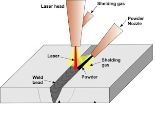
Laser beam welding

Introduction :

Laser beam welding is a technique of welding which used to join multiple pieces of metal through the use of laser. It is frequently used in high volume applications using automation, such as in the automotive industries.

Now we all know that laser is a concentrated beam of coherent monochromatic radiation. Normal white light consists of a number of colours and a number of waves. As a result, it is not possible to use a monochromatic source as laser, provided all waves are of a single phase. This is achieved by means of stimulation. Because of coherency, it is possible to concentrate the laser beam by means of an optical lens to a spot of any desired size without appreciably losing any of its intensity. Thus, the laser beam is a high-energy source of heat to melt a joint for fusion welding in laser beam welding.

Laser beam welding operates in two fundamentally different modes :

  • Conduction limited welding 
  • Keyhole welding 
The mode in which the laser beam will interact with the material it is welding will depend on the power density of the focus laser spot on the workpiece.

How it works?

There are generally two types of laser which are used in welding operation such as solid-state lasers and gas lasers.


In solid-state lasers, light is emitted from a glass on a single crystal that is doped with transition elements such as chromium for ruby. When a beam of normal white light impinges on the crystal, the outer shell electrons of the dope elements go to a higher energy metastable state. They return to the normal state after emitting the extra energy in the form of a photon. All the photons that are stimulated to emit at a given instant will form coherent radiation, which can be concentrated by optical lenses. Thus, the output would be normally in pulses. The power ratings of such units may be up to 2 kW.


In gas lasers, the gas such as carbon dioxide molecules is excited to the higher vibrational energy level by means of an electric discharge. The transition from this high-energy level to the normal level generates the radiation which is coherent and gets focused by means of the usual optical lenses. Continuous-wave gas lasers using carbon dioxide gas with powers up to 20 kW are used for laser beam welding. 


Laser beam welding
With low power lasers typically less than 1 kW, the penetration would not be much and the weld is obtained by means of complete welding of the joint near the surface. But as the power increased because of that the large heat density obtained. That large density causes the metal at the centre of the jet to be vaporized with a keyhole being formed similar to that of electron beam welding. The temperature within this keyhole can reach as high as 25000 0C. This technique permits large welding speeds depending on laser size.  

There are three types of lasers that are commonly used in welding operation such as CO2, Nd: YAG and fibre laser. The Nd: YAG laser light is absorbed quite well by conductive materials, with a typical reflectance of about 20 to 30 % for most metals. Using standard optics, it is possible to achieve focused spot sizes diameter as small as 0.025 mm. On the other side, the COlaser has an initial reflectance of about 80 to 90 % for most metals and requires special optics to focus the beam to a minimum spot size of about 0.075 to 0.100 mm diameter. However, whereas the Nd: YAG lasers might produce power outputs up to 500 watts, the CO2 system can easily supply 10 kW of power and more.


Advantages of laser beam welding :

  • Heat input is close to the in the minimum required to fuse the weld metal, thus heat-affected zones are reduced and workpiece distortions are minimized.
  • Time for welding thick sections is reduced and the need for filler wires and elaborate joint preparations is eliminated by employing the single pass laser welding procedures.
  • No electrodes are required.  
  • LBM being a non-contact process so distortions are minimized and tool wears are eliminated.
  • Welding in areas that are not easily accessible with other means of welding can be done by LBM.
  • The joining of small spaced components with tiny welds very easily because of laser beam can focused on a small area.
  • Wide variety of materials including various combinations can be welded very easily.
  • Thin welds on small diameter wires are less susceptible to burn back than is the case with arc welding. 
  • Metals with dissimilar physical properties, such as electric resistance can also be welded by LBW.
  • No vacuum or X-Ray shielding is required. 
  • Welds magnetic materials also. 
  • Aspect ratios means depth-to-width ratio of the order of 10:1 are attainable in LBM.
  • Faster welding rate.
  • No flux or filler metal required.
  • Single-pass two-side welding. 
  • Shorter cycle and higher up times. 
Limitations of laser beam welding :
  • Joints must be accurately positioned laterally under the beam.
  • Final position of the joint is accurately aligned with the beam impingement point.
  • The maximum joint thickness that can be welded by laser beam is somewhat limited. 
  • The materials have high thermal conductivity and reflectivity like Al and Cu alloys can affect the weldability with lasers. 
  • An appropriate plasma control device must be employed to ensure the weld reproducibility while performing moderate to high power laser welding. 
  • Lasers tend to have low energy conversion efficiency less than 10 percent. 
  • Some weld-porosity and brittleness can be expected, as a consequence of the rapid solidification characteristics of the LBM. 
Laser beam welded parts are often required additional steps before and after the actual weld. we can see this additional steps below :

Process before welding :
  • CAD/CAM product design and weld design.
  • Tooling design and fabrication.
  • Parts cleaning.
  • Strategic Sourcing and Subcontractor Contract Management
Process after welding :
  • Leak test.
  • Metallurgic evaluations.
  • Post weld thermal treatment.
  • Not destructive testing.
You also check it out the :

  • laser beam welding application

Plasma arc welding

Introduction :

In plasma arc welding plasma is the state of the matter when part of the gas is ionized making it a conductor of electric current. It is the state of matter present in between the electrode in an arc. The plasma arc welding closely resembles that of the TIG welding in that it also uses a non-consumable tungsten electrode and a shielding gas such as argon.

The plasma welding process was introduced to the welding industry as a method of bringing better control to the arc welding process in lower current ranges. 

How does it work?


In plasma arc welding, the plasma arc is tightly constrained and a small amount of pure argon gas flow is allowed through the inner orifice surrounding the tungsten electrode to form the plasma gas.


To initiate the arc in PAW, a low current pilot arc is obtained between the electrode and the constricting nozzle which is heated to an extremely high temperature and ionized so that it becomes electrically conductive. The arc in this type of welding is concentrated and straight. and similar to tungsten inert gas welding plasma to transfer an electric arc to a workpiece. The metal to be welded is melted by the intense heat of the arc and metal fuses together thus welding is done.

In plasma welding torch a tungsten electrode is located within a copper nozzle having a small opening at the tip. A pilot arc is produced between the torch electrode and nozzle tip. This arc is then transferred to the metal to be welded.

The plasma gas itself is not sufficient to protect the weld metal therefore, a large volume of inert-shielding gas is allowed to flow through an outer gas nozzle surrounding the inner nozzle. Plasma gases are normally argon. The torch also uses a secondary gas surcharge, argon/hydrogen or helium which assists in shielding the molten weld puddle thus minimizing the oxidation of the weld.

The power source used is DC with electrode negative for better electrode life. 
The actual welding by PAW is done by means of a technique called a keyhole.


Plasma arc welding


Equipment Required List :

  • Power Supply
  • Plasma Console (sometimes external, sometimes built-in)
  • Water re-circulator (sometimes external, sometimes built-in)
  • Plasma Welding Torch
  • Torch Accessory Kit (Tips, ceramics, collets, electrodes set-up gages)
Advantages of plasma arc welding :

  • The main advantages of this are lies in the control and quality produced in the part being welded.
  • The torch design allows for better control of the arc, as well as a higher tolerance for in torch standoff distance.
  • Welds are typically cleaner and smoother in PAW process.
  • Smaller heat affected zone results welds are very strong.
  • Metal deposit rates are high.
Limitations of plasma arc welding :

  • Welding equipment is expensive.
  • Nozzle surrounding the electrode needs a frequent replacement.
  • Relatively high startup costs.
  • High skilled workers required.

Shielded metal arc welding

Introduction :

Shielded metal arc welding is also called as manual metal arc welding. It is the most extensively used manual welding process, which is done with stick electrodes. Though in the USA, its use is decreasing in comparison to the other arc welding process. In India, it still is the most used arc welding process. This process is highly versatile and can be used extensively for both simple as well as complicated joints. 

How it works?

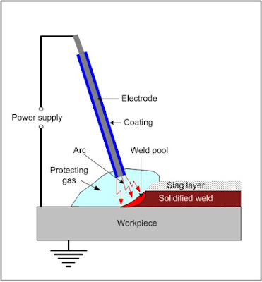
The typical shielded metal arc welding set up with an AC power source. The electrodes for the welding operation should be selected properly, depending on the requirements of the welding.
It can be done with either an AC or DC power source. The typical range of the current usage may vary from 50 to 500 A with voltages from 20 to 40 V.

Shielded metal arc welding uses a metallic consumable electrode of a proper composition for generating arc between itself and the workpiece. The molten electrode metal fills the weld gap and joins the workpiece.

The electrode is coated with a shielded flux of suitable composition. The flux melts together with the electrode metallic core, forming a gas and slag, shielded the arc and weld pool. The flux cleans the metal surface, supplies some alloying elements to the weld and then slag is removed after the solidification.


Shielded metal arc welding

The main points to be considered in this welding process are the following :

  • Composition of the base metal, which determines the electrode composition.
  • Tensile strength of the required joint.
  • The thickness of the base metal. ( for thinner metal the current setting should be lower )
  • Required metal deposition rate.
  • Type of arc welding equipment used.
  • Weld position - Flat, horizontal, vertical or overhead.
Advantages of shielded metal arc welding :

  • A job of any thickness can be welded by shielded metal arc welding accept very small thickness below 3 mm may give rise to difficulties in welding because of their lack of rigidity.
  • Simple, portable and inexpensive equipment.
  • Suitable for outdoor applications.
  • Wide variety of metals welding done by this process.
  • Also, a wide variety of welding positions and electrodes are applicable.

Limitations of shielded metal arc welding :

  • The slow speed of the welding process.
  • The typical weld metal deposition rates may be in the range of 1 to 8 kg/h in the flat position.
  • A lot of electrode material is wasted in the form of unused end, slag and gas.
  • There are some chances of slag inclusion in the bead. 
  • Some precautions are needed to reduce moisture pick-up so that it does not interfere with the welding.
  • Fumes make difficult the process control.