What is belt drive

Introduction :

To transmit power from one shaft to another pulley are mounted on the two shafts. The pulleys are then connected by an endless belt or rope passing over the pulleys. The connecting belt or rope is kept in tension so that the motion of one pulley is transferred to the other without slip. The speed of the driven shaft can be varied by wearing the diameter of the two pulleys. 

What is belt drive?

Belt the drive is a mechanism in which power is transmitted by the movement of a continuous flexible belt. 
A belt may be a rectangular section is known as a flat belt or of the trapezoidal section known as V-belt. In case of a flat belt, the rim of the pulley is slightly crowned which helps to keep the belt running centrally on the pulley rim. The groove on the rim of the pulley of a V-belt is made deeper to take advantage of the wedge action. The belt does not touch the bottom of a groove. Owing to wedging action V-belt needs a little adjustment and transmit more power without sleep as compared to flat belt also multiple V-belt a system using more than one belt in the two pulleys can be used to increase the power transmitting capacity generally these are more suitable for shorter centre distance. Thus, belt drive works on the law of belting. 


Belt drive


Open belt drive :

An open belt drive used when the driven pulley is desired to be rotated in the same direction as the driving pulley.  
Generally, the centre distance for an open belt drive is 14 to 16 metre. If the centre distance is too large, the belt whips vibrate in a direction perpendicular to the direction of motion. For very short at the centre distance, the belt sleep increasing. Both these phenomena limit the use of belts for power transmission.


Open belt drive


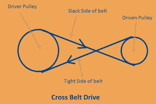
Crossbelt drive :

A the crossed-belt drive is adopted when the driven pulley is to be rotated in the opposite direction to that of the driving pulley.


Crossbelt drive


A cross belt drive can transmit more power than an open belt drive as the angle of wrap is more. However, the belt has to be a band in two different planes and it we are out more. 

Advantages of belt drive :

  • A belt drive is simple and economical.
  • Wide range of speeds is available.
  • In belt drive don't need parallel shaft.
  • Noise and vibration are damped out.
  • Machinery life is increased because load fluctuations are shock-absorbed.
  • Less maintenance cost because no lubrication are required.
  • Belts permit flexibility ranging from high horsepower drives to slow speed and high speed drives so it is highly efficient in use.
  • A flat belt is best for very high-speed drives.
  • This drive is very economical even when the distance between the shaft is very large.
  • Belts will slip under overload conditions this leads the biggest advantages that preventing mechanical damage to shafts, keys, and other machine parts.
  • All the belt drives do not need the pulleys to be maintained at the same height.
Disadvantages of belt drive :
  • Operating temperature is restricted up to 80 to 850C.
  • Heat buildup occurs.
  • Belts can't be used where exact timing or speed is required because of slippage.
  • Because of slipping and stretching the angular velocity ratio is not necessarily equal or constant to pulley diameter ratio.
  • In belt, drive belts are damaged easily by abrasives or heat or some chemicals.
  • Some adjustment of centre distance or use of an idler pulley is necessary for wearing and stretching of belt drive compensation.
  • Speed is limited to usually 35 meters per second.
  • Power transmission is limited to 370 kilowatts.

Applications of adsorption

Applications of adsorption :

  • Activated charcoal is used in gas masks in which all undesirable or toxic gases are observed selectively by charcoal, while purified air passes through its pores. 
  • Activated charcoal is used for removing colouring matter of sugar solution and the decolouration of vinegar. 
  • Silica and Alumina gels are used as an adsorbent for removing moisture and for controlling humidities of room. Silica Gel has been employed for drying air, used in blast surfaces.
  • Charcoal adsorption filters are used for removing organic matter from drinking water.
  • Selective adsorption by alumina, magnesia has been used for separating different pigments by adsorption chromatography. 
  • During arsenic poisoning, colloidal fabric hydroxide is administered. The letter absorbs the arsenic poison and retails it can thus be removed from the body by vomiting. 
  • Fuller's earth is used in large quantities for refining petroleum and vegetable oil due to its good adsorption capacity for unwanted materials. 
  • The phenomenon of adsorption is useful in heterogeneous catalysis Example: contact process, Haber's process, hydro generation of oils based on the adsorption process. 
  • Adsorption the process is used in the production of a vacuum by using activated charcoal in dewar's flask.
  • Lake test for Al+ Lake test for Al+3 is based upon adsorption of litmus colour by Al(OH)3 precipitate. 
  • Mordants used in Dying cloth, adsorb the dye particles, which otherwise, do not speak to the clothes.

Advantages of gear drive

Gear drive is used to transmitting mechanical power from one place to another, often used to convey power to wheels of the bicycle and motorcycles. It is also used in a wide variety of machine apart from the vehicle. Let us have a deep insight into the advantages of gear drive in this article. 

Advantages of gear drive :

  • It is very compact and needs less space.
  • Most convenient for very small centre distances.
  • The velocity ratio will remain constant throughout and any velocity ratio up to 60:1 can be obtained.
  • It has very high efficiency which is very useful in transmitting motion.
  • It will be possible to transmit the power if the axes of the shafts are not only parallel, but even when the axis of the shaft is nonparallel, intersecting, non-intersecting and coplanar or non-coplanar by using different types of gears.
  • They can be used conveniently for transmission of low, medium and high power.
  • It is a reliable service that is a very good advantage.
  • Gears are employed for a wide range of applications like in watches, precision measuring instruments, machine tools, gearboxes fitted in automobiles, aero engines, etc.
  • Gears may be cast integral with the shafts if required. 
  • In a wide range of metallic and non-metallic materials, gears can be cast.
  • It provides a large range of speed and torque for same input power. 
  • It is compact and needs less space.

Disadvantages of gear drive

Gear drive is used to transmitting mechanical power from one place to another, often used to convey power to wheels of the bicycle and motorcycles. It is also used in a wide variety of machine apart from the vehicle. Let us have a deep insight into the disadvantages of gear drive in this article. 

Disadvantages of gear drive :

  • It is very difficult to manufacture the gears because in manufacturing gears the specials equipment are needed which is costly so they are not economical.
  • They are not suitable for very large centre distances of shafts.
  • They always require proper lubrication.
  • If there may any error during manufacturing then it may cause a big accident.
  • If a large number of gear wheels used in gear trains that increases the weight of the machine.
  • Noise and vibrations will be more at high speeds. 
  • Use of a large number of gear wheels in gear trains increases the weight of the machine.

Disadvantages of chain drive

A chain drive is positive drives, so the velocity ratio remains constant and no-slip occurs, making it suitable mainly for the shorter centre distance. The chain drive is a way of mechanical power transmission mainly used in a motorcycle. Let us check some disadvantages of a chain drive in this article. 

Disadvantages of a chain drive : 

  • It is heavier as compared to belt drive.
  • In chain drive, both driving and driven shafts are perfectly inclined.
  • It requires accurate mounting and good lubrication.
  • Higher initial cost because production cost for the chain is high.
  • Weight of a chain is high and if the chain is dry it becomes noisy.
  • Lubrication of its parts is required.
  • There are gradual stretching and an increase in the length of chains. Some of its links need to be removed from time to time.

Advantages of chain drive

A chain drive is positive drives, so the velocity ratio remains constant and no-slip occurs, making it suitable mainly for the shorter centre distance. The chain drive is a way of mechanical power transmission mainly used in a motorcycle. Let us check some advantages of a chain drive in this article. 

Advantages of a chain drive :

  • Positive and non-slip drive.
  • Efficiency is high for a shorter distance.
  • It is used generally up to 3 meters but some special cases it is up to 8 to 10 meters also.
  • Permits high-velocity ratio up to 8:1 because of no-slip takes place in this drive.
  • Transmit more power than belt drive.
  • Maintenance is low.
  • Chains are made up by metal so chain occupies lesser space than belt drive and rope drive.
  • It permits higher speed ratio of 8 to 10 in one step.
  • It can be operated under any atmospheric conditions.
  • It has the ability to transmit motion to various shafts by only one chain.
  • Easy to install and repair.
  • Good service life.
  • Lesser loads are put on the shafts.

Advantages and disadvantages of belt drive

A Belt drive is one of the most common and effective devices of transmitting motion from one shaft to another by means of a thin, in-extensible band running over the two pulleys. It is generally used to employed the rotary motion is to be transmitted between the two shafts. 
So for the above reason belt drive has more advantages. Let us check it out one by one below.


Advantages of belt drive :

  • A belt drive is simple and economical.
  • A wide range of speeds is available.
  • In belt drive don't need parallel shaft.
  • Noise and vibration are damped out.
  • Machinery life is increased because load fluctuations are shock-absorbed.
  • Less maintenance cost because no lubrication is required.
  • Belts permit flexibility ranging from high horsepower drives to slow speed and high speed drives so it is highly efficient in use.
  • A flat belt is best for very high-speed drives.
  • This drive is very economical even when the distance between the shaft is very large.
  • Belts will slip under overload conditions this leads the biggest advantages that preventing mechanical damage to shafts, keys, and other machine parts.
  • All the belt drives do not need the pulleys to be maintained at the same height.

Disadvantages of belt drive :

  • Operating temperature is restricted up to 80 to 850C.
  • Heat buildup occurs.
  • Belts can't be used where exact timing or speed is required because of slippage.
  • Because of slipping and stretching the angular velocity ratio is not necessarily equal or constant to pulley diameter ratio.
  • In belt drive, belts are damaged easily by abrasives or heat or some chemicals.
  • Some adjustment of center distance or use of an idler pulley is necessary for wearing and stretching of belt drive compensation.
  • Speed is limited to usually 35 meters per second.
  • Power transmission is limited to 370 kilowatts.

Advantages and disadvantages of V-belt drive

The V-belt drive is also called a friction drive. The shape of the V-belt is somewhat trapezoidal. The pulleys also have tapered sides forming v groove in which the belt sits thus V-belt does not get many possibilities to slide away from the pulleys. Let us have a deep insight into the pros and cons of V-belt drive in this article. 

Advantages of V-belt drive :

  • Positive drive as slip between belt and pulley is negligible.
  • No joint troubles as V-belt are made endless.
  • Operation is smooth and quiet.
  • High-velocity ratio up to 10 can be obtained.
  • It can be easily installed and removed.
  • Due to wedging action in the grooves, limiting ratio of tensions is higher and thus, more power transmission.
  • It may be operated in either direction with a tight side at the top or bottom.
  • Multiple V-belt drives increase the power transmission manifold.
  • Slip between the belt and the pulley is negligible.
  • The axis can be vertical or horizontal or inclined.
  • They can dampen vibration.

Disadvantages of V-belt drive :

  • It can not be used for large centre distances.
  • In V-belt construction of pulleys is not simple.
  • V-belt is not as durable as a flat belt.
  • It costlier as compared to the flat belt.
  • V-belt drive can't be used for long distances due to a greater weight per unit of length.
  • It may be not applicable to synchronous machines because they are not free from creep.
  • The centrifugal tension prevents the use of belts at speeds below 5 m/s and above 50 m/s.

Difference between laser and electron beam welding

What is laser beam welding?

A welding technique used to join pieces of metal or thermoplastics through the use of a laser is called laser beam welding. 

What is electron beam welding?

Electron beam welding is a fusion welding process in which a beam of high-velocity electrons is applied to the material and thus welding is done. 

Electron beam welding and laser beam welding are two very popular methods used for welding. Let us have a deep insight into the difference between both of welding process.

Difference between laser and electron beam welding : 

  • EBW is performed in a high vacuum environment, which is most suitable for titanium, refractory metals and flammable metals. while LBW is not performed under a vacuum environment it usually performed with shielding gas such as argon or nitrogen.
  • EBW is usually narrower than the laser weld. The LBW weld is particularly suited for high volume application. 
  • EBW cost is higher than the LBW.
  • In EBW X-rays is generated while not generated in LBW.
  • Size of the workpiece is limited because of vacuum size in EBW while LBW can weld any size of workpieces.
  • The power efficiency of EBW is 80 to 90 % and 7 to 10 % is for LBW. 
  • Penetration is deep in case of EBW while lake penetration in LBW.

Electron beam welding advantages and disadvantages

Electron beam welding is a powerful beam welding process. The heat source in electron beam welding for melting joints is a focused beam of high-velocity electrons. The electron beam upon impinging on the workpiece releases the necessary heat by converting its kinetic energy. 


Electron beam welding is a fusion welding process in which a beam of high-velocity electrons is applied to two materials to be joined. It is often performed under vacuum conditions to prevent dissipation of the electron beam. Let us have a deep insight into the pros and cons of electron beam welding in this article. 

Advantages of electron beam welding :

  • No gas contamination.
  • Deepest weld penetration.
  • The depth-to-width ratios between 10:1 to 30:1 can be easily realized with electron beam welding.
  • It is done in a vacuum environment so clean welding environment is guaranteed.
  • Small heat affected zone similar to laser beam welding.
  • It allows welding of titanium, refractory metals and flammable metals.
  • Widely used in many industries.
  • Filler metal or flux are not needed to be used in this process of welding.
  • No additional processing is required.
  • The process can be used at higher welding speeds, typically between 125 to 200 mm/s.
  • It is also possible to closely control this penetration by controlling the accelerating voltage, beam current and beam focus. 
  • The heat liberated is low and also is in a narrow zone. Thus, the heat-affected zone is minimal as well as weld distortion is eliminated.

Disadvantages of electron beam welding :

  • Due to vacuum enclosure, high initial set up cost.
  • Size is restricted by a vacuum chamber only small to medium size items can be welded.
  • Sometimes this process required complex tooling.
  • X-rays generated during welding.
  • Longer cycle time than laser beam welding so this process is time-consuming.

Electron beam welding applications

Electron beam welding process is done under the vacuum, the welds are clean and free from oxides and nitrides so this process posses various application.


Application of electron beam welding : 

  • High depth-to-width ratio eliminates multiple-pass welds. Penetration is 0.001 to 2 inches.
  • Welds up to 95% of the strength of the base material.
  • By using this process welds in close proximity to heat-sensitive components because of minimizes shrinkage and distortion.
  • Precise control and repeatability at speeds from 1 to 200 inches per minute.
  • This process permits welding of refractory and dissimilar metals not weldable with another conventional welding process.
  • Electron beam welding is ideal for sealing of pre-evacuated housings and electrical components.
  • In power generation, vacuum system and medical field. 
  • In aerospace sensors like jet engine components, transmission components, parts of structures.
  • In space sensors like titanium tanks.
  • In automotive industries gears, transmission part, parts of a turbocharger.
  • Welding of metals with dissimilar melting points for example - steel to nickel alloys, copper to nickel alloys, copper to steel, tantalum to tungsten.

Laser beam welding advantages disadvantages

Laser beam welding is a technique of welding which used to join multiple pieces of metal through the use of laser. It is frequently used in high volume applications using automation, such as in the automotive industries. Let us have a deep insight into the pros and cons of laser beam welding in this article.

Advantages of laser beam welding :

  • Welding of complicated joint geometry.
  • Precise working with the exact placing of the energy spot done in laser beam welding.
  • Low heat application, therefor minor changes in microstructure.
  • Low thermal distortion.
  • Cavity free welds.
  • Low post-weld operation time.
  • Large working distance is also possible. 
  • Heat input is close to the in a minimum required to fuse the weld metal, thus heat-affected zones are reduced and workpiece distortions are minimized.
  • Time for welding thick sections is reduced and the need for filler wires and elaborate joint preparations is eliminated by employing the single-pass laser welding procedures.
  • No electrodes are required.  
  • LBM being a non-contact process so distortions are minimized and tool wears are eliminated.
  • Welding in areas that are not easily accessible with other means of welding can be done by LBM.
  • The joining of small spaced components with tiny welds very easily because of a laser beam can focus on a small area.
  • Wide variety of materials including various combinations can be welded very easily.
  • Thin welds on small diameter wires are less susceptible to burn back than is the case with arc welding. 
  • Metals with dissimilar physical properties, such as electric resistance can also be welded by LBW.
  • No vacuum or X-Ray shielding is required. 
  • Welds magnetic materials also. 
  • Aspect ratios mean depth-to-width ratio of the order of 10:1 are attainable in LBM.
  • Faster welding rate.
  • No flux or filler metal required.
  • Single-pass two-sided welding. 
  • Shorter cycle and higher up times. 

Disadvantages of laser beam welding :

  • The welding equipment is expensive so the cost for this process is high.
  • If the filler material is necessary but in this process limited amount produced with the use of filler material so relatively expensive.
  • There are also a few post welding operations. 
  • Joints must be accurately positioned laterally under the beam.
  • The final position of the joint is accurately aligned with the beam impingement point.
  • The maximum joint thickness that can be welded by laser beam is somewhat limited. 
  • The materials have high thermal conductivity and reflectivity like Al and Cu alloys can affect the weldability with lasers. 
  • An appropriate plasma control device must be employed to ensure the weld reproducibility while performing moderate to high power laser welding. 
  • Lasers tend to have low energy conversion efficiency less than 10 percent. 
  • Some weld-porosity and brittleness can be expected, as a consequence of the rapid solidification characteristics of the LBM. 

Laser beam welding application

Application of laser beam welding :

  • Used in aerospace and automotive applications for welding a high-strength aluminium alloys and titanium alloys.
  • Used in welding a magnesium alloys parts.
  • Welding of non-porous seams in medical technology.
  • Precision spot welding in electronics or jewellery industries.
  • To welding complete car bodies in the automobile industries.
  • To deposit welding in tool and mould-making.
  • Pressed components to hydroformed tubes or extrusions.
  • Production of node structures in aluminium alloy castings or extrusions.
  • Production of stiffened structures consisting of the welded sheet.
  • Recent advancements in scanner optical configurations, scanner controls, and real-time interfaces to optical sensors are also application of laser beam welding.

What is linkage

What is linkage :

A linkage is obtained if one of the links of a kinematic link is fixed to the ground.

The action of linking or the state of being linked two links is known as linkage.

In other words, the linkage is a system of links.


Linkage

What is kinematic pair

Kinematic pair :

A kinematics pair of simply a pair is a joint of two kinematic links that have relative motion with respect to each other. 
When two links in a machine are in contact with each other, they form a pair. Each individual links of a mechanism form a pairing element. 

A degree of freedom of kinematic pair is given by the number of independent coordinates required to completely specify the relative movement between the pair of two links.

Types of kinematic pair :

Kinematic pair can be classified according to :
  • The nature of the contact.
  • The nature of mechanical constraint.
  • The nature of relative motion.
Kinematics pairs according to nature of contact :
  • Lower pair 
  • Higher pair 
Kinematic pairs according to the nature of mechanical constraint :
  • Closed pair 
  • Unclosed pair 
Kinematics pair according to nature of relative motion :
  • Sliding pair
  • Turning pair
  • Rolling pair 
  • Screw pair
  • Spherical pair 

Types of kinematic pairs

Types of kinematic pair :

Kinematic pair can be classified according to :
  • The nature of the contact.
  • The nature of mechanical constraint.
  • The nature of relative motion.
Kinematics pairs according to nature of contact :

Lower pair: A pair of links having surface area contact between the member is known as a lower pair.
In the lower pair, the contact surfaces of the two links are similar.

For example : 
  • Nut turning on a screw shaft.
  • Shaft rotating in a bearing.
  • All pairs of slider-crank mechanism.
  • Universal joint.
Higher pair: A pair has a point or line contact between the links is known as a higher pair.
In the higher pair, the contact surfaces of the two links are dissimilar.

For example : 
  • Rotating on a surface 
  • Cam and follower pair 
  • Tooth gear 
  • Ball-bearing  
  • Roller bearings 
Kinematic pairs according to the nature of mechanical constraint :

Closed pair: When the elements of a pair are held together mechanically it is known as a closed pair.
The two elements are geometrically identical one is solid and full and other is hollow or open. The letter not only envelops the former but also and closed it. 
All the lower pairs and some of the higher pairs are closed pair.
A screw pair belong to the closed pair category also. 
  
Closed pair

Unclosed pair: When two links of a pair are in contact but due to some spring action or force of gravity, they constitute an unclosed pair.
In this, the links are not held together mechanically. 


Unclosed pair

Kinematics pair according to nature of relative motion :

Sliding pair: If two links have a sliding motion related to each other, they form the sliding pair. 

For example - A rectangular rod in a rectangular hole in a prism


Sliding pair


Turning pair: When one link has a turning on revolving motion relative to others, they constituted a turning pair.
They also called revolving pair.

For example - In a slider-crank mechanism all pairs except the slider and guide pair are turning pair.
A circular shaft revolving inside a bearing.


Turning pair


Rolling pair: When the link of a pair has a rolling motion relative to each other, they form a rolling pair.

For example - Rolling wheel on a flat surface
Ball and roller bearing in a ball bearing 
The ball and shaft constitutive and rolling pair where is the ball and the bearing is a second rolling pair.

Rolling pair

Screw pair : If two mating links have a turning as well as sliding motion between them, they form of screw pair. This can be achieved by cutting matching threads on the two links.

For example - The lead screw and the nut of a late is a screw pair.

Screw pair

Spherical pair : When one link in the form of sphere turn inside a fixed link, it is a spherical pair.

For example - The ball and socket joint


Spherical pair

Types of constrained motion

Types of constrained motion :
  • Completely constrained motion 
When the motion between two elements of a pair is indefinite direction irrespective of the direction of the force applied it is known as completely constrained motion.
The constrained motion may be linear or rotary.

Example of completely constrained motion :
  • The sliding pair 
  • The turning pair 
In sliding pair, the inner prism can only slide inside the hollow prism.
In case of the turning pair, the inner shaft can have only rotary motion due to the collar at the ends. 
In each case of force has to be applied in a particular direction force required motion.

Constrained motion
  • Incompletely constrained motion 
When the motion between two elements of a pair is possible in more than one direction and depend upon the direction of the force applied that motion is known as incompletely constrained motion. 

Example of incompletely constrained motion :
  • The inner shaft may have sliding or rotary motion depending upon the direction of the force applied if the turning pair does not have a collar.
Each motion is independent of the other.

Incompletely constrained motion
  • Successfully constrained motion 
When the motion between two elements of a pair is possible in more than one direction but with the using of some external means motion is made to have only in one direction so that motion is known as successfully constrained motion.

Example of a successfully constrained motion :
  • A shaft in a footstep bearing may have vertical motion apart from rotary motion but due to the load applied on the shaft, it is a constraint to move in that direction and thus is successfully constrained motion.
  •  A Piston in a cylinder of an internal combustion engine is made to have only reciprocating motion and no rotary motion due to constraining of the piston pin. 
  • The value of an IC engine is kept on the seat by the force of a spring.
Successfully constrained motion

Types of joints in kinematics

Types of joints :
  • Binary joint 
  • Ternary joint 
  • Quaternary joint 
Binary joint :

If two links are joint at the same connection it is known as a binary joint.

Ternary joint :

If three links are joint at a connection it is known as a ternary joint. 
It is considered equivalent to the two binary joints since fixing of anyone link constitute two binary joints with each of the other two links.

Quaternary joint :

If four links are joint at a connection it is known as a quaternary joint.
It is considered equivalent to three binary joints since fixing of anyone link constitutes three binary joints.

If n number of links are connected at a joint, it is equivalent to ( n -1 ) binary joints. 

What is kinematic link

What is the kinematic link?

A mechanism is made of a number of resistant bodies out some may have motions relative to each other. A resistant body or a group of resistant bodies with rigid connections preventing their relative movement is known as a link.

This link is also known as kinematic link or element.

The link can be classified into binary, ternary and quaternary depending upon the end on which revolute or turning pairs can be placed.


Kinematic link

A link may also be defined as a member or a combination of members of a mechanism, connecting other member and having motion relative to them. Thus, a link may consist of one or more resistant bodies. 

For example, a slider-crank mechanism consists of four links: frame and guides, crank, connecting rod and slider. however, the frame may consist of bearings of for the crankshaft. The crank link may have a crankshaft and flywheel also, forming one link having no relative motion of this.

Mechanism and machine

In this article, we will discuss the mechanism and machine.

What is the mechanism :

When one of the links of a kinematic link is fixed, then the chain is known as a mechanism.

A mishmash of a number of bodies assembles in such a way that it causes the constrained and predictable motion to the other is known as a mechanism.
Thus, the function of the mechanism is to transmit and modify a motion.

What is a machine :

Machine is a mechanism which receives energy and transforms it into some useful work.

A collection of mechanisms which, transmits and modifies available mechanical energy into some kind of desired work and also imparting definite motions to the parts is called machine.

It is neither a source of energy nor a producer of work that helps in proper utilization of the same. The motive power has to be derived from external sources.

Example :

A slider-crank mechanism converts the reciprocating motion of a slider into rotary motion of the crank or vice-versa. however, when it is used as an automobile engine by adding valve mechanism it is it becomes a machine which converts the available energy into the desired energy. 
 

Some other examples of mechanisms are typewriter, clocks, watches, spring toys etc. 

In each of these force or energy provided is not more than what is required to overcome the friction of the path and which is utilized just to get the desired motion of the mechanism not to obtain any useful work.

Some useful notes :

A machine is tangible, but the mechanism is not. Only the effect of the mechanism is observable.

In a simple way, a mechanism is a system that is followed by a machine to achieve the particular function while machine is a combination of tools and parts that performs specific functions at the expense of energy.

For Example :

We think a car is a machine. It made of various mechanisms such as the wipers, piston and crankshaft, differential.
All this parts are simple a mechanism following below : 

  • Wipers is a 4 link crank lever mechanism
  • Piston and crankshaft is a slider crank mechanism
  • Differential is a gear mechanism. 

Thus a machine is made of number of mechanism to carryout a particular task.