Advantages and disadvantages of die casting

Die casting process is widely used in the manufacturing sector and automobile industries because of many advantages of the die casting process. Let us have a deep insight into the pros and cons of die casting. 


Advantages of die casting : 

  • Because of the use of movable cores, it is possible to obtain complex casting than that by permanent mould casting.
  • Production rate is very high. The typical rate could be 200 pieces per hour.
  • Die casting process is completely automated.
  • Very small thickness can be easily filled because the liquid metal is injected at high pressure.
  • Very good surface finish in order of 1 micron can be obtained.
  • The surface generated by the die casting process is directly electroplated without further processing.
  • Dimensional tolerance is very close in order n between +0.08 to -0.08 can be obtained.
  • The die has a long life.
  • Inserts can be readily cast in place.
  • This process is very economical for large scale production.
  • It will give better mechanical properties compared to sand casting.

Disadvantages of die casting : 

  • Material limitations all material and alloy can not be cast. 
  • The cost of the machine dies and other equipment is high. 
  • Not economical for small quantity production. 
  • Heavy casting can't be cast by this process.
  • Limited to high-fluidity metals.
  • The air in the die cavity gets trapped inside the casting causes a problem of porosity.

What is die casting

Die casting is a permanent mould manufacturing process. It was first developed in the early 1900s. Die casting is a widely spread technique for which the metal is forced into the mould cavity under high pressure and produced geometrical complex metal parts through the use of reusable moulds is called dies. In this process involves furnace, metal, die casting machine and die. The mould cavity is like intricate in designs that enable in producing complex shapes with good surface finish, high accuracy and attractiveness.

Working principle of die casting :

Die casting process complete in five stages that we can discuss below :
  1. Clamping
  2. Injection
  3. Cooling
  4. Ejection
  5. Trimming
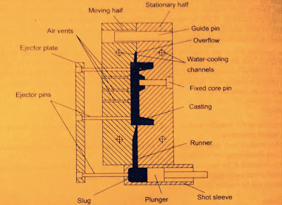
Above mentioned five stages this process the die consists of two parts. one part is called stationary half or cover die which is fixed to the die casting machine. The second part is called moving half or ejector die that is moved out for the extraction of the casting. The casting cycle starts when two parts of the die are apart. The lubricant is sprayed on the die cavity manually or automatically because casting will not stick to the die. The two die halves are closed and clamped. The required amount of metal is injected into the die. After the casting is solidified under the pressure the die is opened and casting is ejected. It will also have cooling channels to extract the heat of the molten metal to maintain proper die temperature.

Die casting

The die casting machine is two types :
  1. Hot chamber die casting
  2. Cold chamber die casting 
In between two types, the main difference is that in the hot chamber machine, the holding furnace for the liquid metal is integral with the die casting machine. wherein cold chamber machine, the metal is melted in a separate furnace after that metal is poured into the die casting machine with a ladle for each casting cycle is called shot.

Hot chamber dies casting machine :


Hot chamber process is also called gooseneck casting. Hot chamber machines are used for alloys with low melting temperatures, such as zinc, tin, and lead. The gooseneck is made of grey alloy or ductile iron or of cast steel. The operating sequence of this process is typical injection pressures for a hot chamber die casting machine are between 1000 and 5000 psi. After the molten metal has been injected into the die cavity and then the plunger remains down, holding the pressure while the casting solidifies. After solidification, the hydraulic system retracts the plunger and the part can be ejected by the clamping unit.  the plunger moves back returning the used liquid metal to the gooseneck. The casting which is in the ejector die is now ejected then the plunger uncovers the filling hole, letting the liquid metal from the furnace to enter the gooseneck.
In the hot chamber die casting process the direct immersion in the molten metal allows for quick and convenient mould injection, it also results in increased corrosion susceptibility. Because of these characteristics, the hot-chamber die casting process is best suited for applications that utilize metals with low melting points and high fluidity. Good metals for the hot-chamber die casting process include lead, magnesium, zinc and copper. 

Cold chamber dies casting machine :

The hot chamber process is used for most of the low melting temperature alloys while materials such as aluminium and brass. High melting temperature makes it difficult to cast them with the use of a hot chamber process because gooseneck of the hot chamber machine is continuously in contact with the molten metal.
In the cold chamber process, the molten metal is poured with a ladle into the shot chamber. this process reduces the contact time between the liquid metal and the shot chamber.
The operation is similar to that of the hot chamber process start with the spraying die lubricants throughout the die cavity and closing the die when molten metal is ladled into the shot chamber of the machine either manually or by hand or by means of the auto ladle. Then plunger forces the metal into the die cavity and maintains the plunger the pressure till it solidifies then die opens. The casting is ejected. At the same time plunger returns to its original position and completing the operation.
For hot chamber die casting characteristics is too corrosive for the immersion design while the cold-chamber process can be an excellent alternative. 

Die design :

Hot-working tool steels are normally used for the preparation of the dies, die inserts and cores. The die must allow the molten metal to flow easily into all of the cavities. Equally important is the removal of the solidified casting from the die, that is why the draft angle must be applied to the walls of the part cavity. The design of the die must also accommodate any complex features on the part such as undercuts will require additional die pieces. 

  • For zinc alloy, the normal die material is AISI P20 for low volume and H13 for high volume.
  • For aluminium and magnesium H13 and H11 are used.
  • For copper alloy H20, H21 and H22 are used as die material.
High-grade tool steel is the most common and is typically used for 100-150,000 cycles. Steels with low carbon content are more resistant to cracking and can be used for 1,000,000 cycles.

Benefits of the die casting process :
  • High quality :
Parts which are produced by this process have a long service life and its quality is high.
  • High reliability :
By this process, uniform parts are produced and all are highly reliable.
  • Quick production :
In that process just die casting tooling is required after produced one part this process is quick as compared to another manufacturing process of making uniform parts.
  • Minimal assembly :
Assembled of parts that are used in die casting machine are easy.
  • Versatile design :
Die casting application :
  • It is suitable for casting medium-sized parts with complex details.
  • It is widely used in manufacturing commercial, industrial products, automobile industries and aerospace.
  • The typical products like carburettors, crank-cases, magnetos, handlebar housing, other parts of scooters, motorcycles and mopeds, zip fasteners and gears.
Properties and characteristics of the die casting process :
  • Parts manufactured by this process are close tolerance, very high surface finish and thin intricate walls.
  • Production rate is very high.
  • Equipment cost for die casting is generally high but its assembly is easy.
  • This process is highly automated so the labour cost is low.
  • Parts that manufactured by this process are with superior mechanical properties because of rapid cooling.
  • Ejector pins will usually leave small round marks on the metal casting so this will be observed on the surface of manufactured parts.
Because of these properties and characteristics, this process has many advantages and it is widely used in manufacturing industries
Operation of shaper machine

The different operation which a shaper can perform are as follows :
  1. Machining horizontal surface
  2. Machining vertical surface
  3. Machining angular surface
  4. Cutting slot grooves and keyways
  5. Machining splines or cutting gears
  6. Machining irregular surface
  7. Dovetail slides
  8. Producing contour of concave/convex or a combination of these
Machining horizontal surface :

A shaper is mostly used to machine a flat surface on a work piece held in a vice. After work is properly held on the table the tool is set in the tool post. The table is raised until there is a clearance of 25 to 30 mm between tool and work piece. then the length of the stroke is adjusted. proper cutting speed and feed are adjusted. then both roughing and finishing cut are perform on the shaper machine.

Machining vertical surface :

A vertical cut is made while the end of the work piece, squaring up a block or cutting shoulder. The work is mounted on the table and the surface to be machined is carefully aligned with the axis of ram. A side cutting tool is set on the tool post and the position and length of stroke are adjusted. The vertical slide is set exactly zero position and the apron is swivelled in a direction away from the surface being cut.

Machining angular surface :

An angular cut is made at any angle other than a right angle to the horizontal or to the vertical plane. work is set on table vertical slide of the tool head is swivelled to the required angle either towards left or right. Then down feed is given by rotating the down feed screw. thus the angular surface being machined.


Working principle of shaper machine

Working Principle:

Shaper machine works on quick return mechanism.

First of all the work piece is rigidly fixed on the machine table. 
The single point cutting tool held properly in the tool post and it is mounted on a reciprocating ram. 
The reciprocating motion of the ram is obtained by a quick return motion mechanism. As the ram reciprocates, the tool cuts the material during its forward stroke. 
During the return stroke, there is no cutting action and this stroke is called the idle stroke. 
The forward and return strokes constitute one operating cycle of the shaper.
So by this operation forward and return both stroke machining is done.
The reciprocating movement of the ram and the quick return mechanism of the machine are usually obtained by any one of the following methods :
  • Crank and slotted link mechanism
  • Whitworth quick return mechanism
  • Hydraulic shaper mechanism

Types of shaper machine

Types of shaper machine:

1. According to the type of mechanism used  for giving reciprocating motion to the ram :


  • Crank type
  • Geared type
  • Hydraulic type

2. According to the position and travel of ram :

  • Horizontal type
  • Vertical type
  • Travelling head type
3. According to the type of design of the table :

  • Standard shaper 
  • Universal shaper 
4. According to the type of cutting stroke :

  • Push type
  • Draw type

Parts of shaper machine

Main parts of shaper machine :

Shaper machine

Base :
The base is the main body of the machine. It consist of all elements of the machine. The bed may be rigidly bolted to the floor of the shop or on the bench according to the size of the machine.
The base is made of cast iron to resist vibration and take up high compression load.

Column :
The Column is a box it can be mounted upon the base.
It provides the housing for the crank slider mechanism and also encloses the ram driving mechanism.
Two accurately guideways are provided on the top of the column on which the ram reciprocates.

Crossrail :
The Crossrail is mounted on the front vertical guideways of the column.
A horizontal cross feed screw which is fitted within the Crossrail and parallel to the top guideways of the column.
It attaches with some cross-movement mechanism.

Saddle :
The saddle is mounted on the Crossrail which holds the table firmly on its top.
Crosswise movement of the saddle by rotating the crossfeed screw by hand or by the power to move sideways.

Clapper Box :
The Clapper box carries the tool holder.
It provides clearance for the tool in return stroke.
It also prevents the cutting edge dragging the work piece while return stroke and prevents tool wear.

Table :
The table is bolted to the saddle receives crosswise and vertical movements from the saddle and Crossrail. It is the metal body attached over the frame.
The main function of the table is to hold the work piece and vice over it.
T slots which used to clamp vice and work piece over it.

Ram :
Ram is the main part of shaper machine.
The ram is a reciprocating member of shaper machine.
Ram is semi-cylindrical in shape and heavily ribbed inside to make it more rigid.
Ram is made by cast iron and moves over ways on the column.
It attached by the rocker arm which provide it motion in the crank driven machine and if the machine is hydraulically driven it attached by hydraulic housing.

Toolhead :
Toolhead is situated at the front of the ram.
The main function of it is to hold the cutting tool.
The cutting tool can be adjusted on it by some of the clamps.

Stroke adjuster :
It is attached below the table.
It is used to control the stroke length which further controls the ram movement.

Table supports :
These are attached front side of the table and used to support the weight of the table during working.

Advantages of hydraulic shaper

Shaper is a type of machine which, using hydraulic power, provide linear relative motion between the workpiece and single-point cutting tool to a linear path. Under high pressure, oil is pumped into the piston-fitted operating cylinder. This machine gives the following advantages. 

Advantages of hydraulic shaper : 

  • The cutting speed and return speed of this shaper is practically constant throughout the stroke thus work done is uniform during the cutting stroke.
  • The reversal of the ram is obtained quickly without any shock as the oil on the other end of the cylinder provides cushioning effect.
  • An infinite number of cutting speeds may be obtained and its control is also easier. speed range varies from zero to the maximum value.
  • Because of the high rate of return speed, a greater number of cutting strokes may be available within the range of cutting speed.
  • The relief valve ensures safety to the tool and the machine when the machine is overloaded.
  • Wide range of speed can achieve by controlling the fluid flow rate to shaper ram. 
  • Shock and vibration levels can reduce. 
  • Higher load-carrying capacity. 
  • Fluid on both sides of the ram provides a cushioning effect. 
  • Highly efficient. 

Advantages of vertical boring machine over lathe machine

The vertical boring machine may be looked like a vertical lathe with its headstock resting on the floor and its large faceplate or chuck lying in a horizontal plane. This specified vertical boring machine design offers some advantages over a lathe machine. Let us have a deep insight into the advantages below. 

Advantages of a vertical boring machine :

  • Large diameter and heavy workpiece may be set up more conveniently and quickly than on lathe machine.
  • The table and the work it carries rotate in a horizontal plane, and there is no overhang as in the lathe spindle, and any chance of bending the spindle which supports the heavy workpiece is eliminated.
  • The diameter of the table may be designed as large as possible to support large workpieces.
  • Multiple tooling may be adapted in case of a vertical boring machine with its turret type tool post, as a result, increasing the rate of production.

Vertical boring machine

A vertical boring machine is particularly adapted for holding and machining the large, heavy workpiece.
On vertical boring machine following work are done :
  • Large gear blanks
  • Locomotive and rolling stock tires
  • Steam and water turbine castings
  • Flywheels
  • Large flanges and number of circular-shaped parts
A vertical boring machine can take an only a circular cut.

The vertical boring machine is of two types :
  • Vertical turret lathe
  • Standard vertical boring machine
Vertical boring machine parts :
  1. Bed
  2. Table
  3. Housing
  4. Crossrail
  5. Tool-head assembly
Vertical boring machine

Size of vertical boring machine :
Its size is specified by the diameter of its table or chuck expressed in mm.
The size of vertical turret lathe varies from 600 to 2000 mm. 
The size of a standard vertical boring machine is as high as 6000 mm.

Vertical boring machine tools :
The vertical boring machine tools are similar to lathe tools.
For boring operation, the clearance angle of the tool is greater than in turning or facing tool.

Vertical boring machine operation :
A vertical boring machine may generate a horizontal flat surface.
It can also produce cylindrical turned surface, bore internal hole, perform cutting off, necking or forming operation, and generate internal or external taper surface.

Difference between reaming and boring

Reaming and boring is a similar process and use for the same purpose but just a minor difference between them. Reaming used to finish the hole previously drill whereas boring used to enlarge the hole previously drilled. 

Let us have a deep insight into the comparison between those two similar processes and also check the difference between them. 


Difference between reaming and boring : 

  • Reaming is a process of sizing and finishing the already drilled holes while boring processes for producing holes of larger diameter compared to drilling.
  • When compared to boring, a reamer holds tighter tolerances for longer periods of time because the cutting is generally spread out over multiple flutes.
  • Boring operation is done on lathe or milling machine also whereas reaming operation on the same types of machines as drilling.
  • In boring every time a hole has increased the size of a hole is not necessarily the same but in reaming also every time the hole is increased but the size of the hole is the same.
  • In reaming, machinists may use hand or machine reamers depending on the job they are performing while boring a workpiece may be held in a 3, 4, or 6 jaw chuck and collets.
  • Reaming uses multi teeth cutter while boring uses a single tooth cutter.
  • Reaming process MRR is comparatively lower than boring. 
  • Reaming produced a highly finished surface than boring. 
  • The cutting tool used for boring is boring bar while reamer is used for reaming. 

Jig boring machine

The jig boring machine is the most accurate in all type of boring machine. Jig boring machine first developed in the year 1910 in Switzerland. The real jig borer was first built in the year 1917 by Pratt and Whitney.

Jig boring machine is now used for the production of jigs, fixtures, tools and other precision parts which require a high degree of accuracy.
They have the highest accuracy through rigidity, low thermal expansion and measuring distance for accurately locating and spacing holes.

Jig boring machine is a metal cutting machine for finishing holes, planes and slots with a highly precise location of centres or surfaces without the use of special attachments for tool alignment.

In jig boring machine machining accuracy is very high within a range of 0.0025 mm. 
Jig boring machine
The spindle and other parts of the machine are extremely rigid to resist deflection and the vibration is minimum.
The spindle runs in preloaded antifriction bearings.
The jig boring machine requires temperature-controlled rooms for operation where temperature can be maintained constant.

Types of jig boring machine :

There are two types of jig boring machine :

  1. Vertical milling machine type
  2. Planer type
Methods of locating holes in the jig boring machine :

Accurate positioning is essential for producing accurate jigs, fixture, dies etc.
The most important operation in a jig boring machine is the accurate way of positioning a hole that can be done by one of the following methods :
  1. Lead screw method
  2. Mechanical and electrical gauging method
  3. Optical measuring method

Jig boring machine operations :
  • The jig boring machine primarily designed to produce precision dies, jigs and gauges.
  • They also used as measuring machine to check up a job already manufactured in other machines.
  • Also used in enlarging holes.
  • Single point tools enables maximum accuracy in locating holes and give a better surface finish.
  • Jig boring machine operated by highly skilled workers.

Multiple head type horizontal boring machine

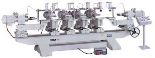
Multiple head type horizontal boring machine resembles a double housing planer or a Plano-miller.

The table is supported on a long bed on which it reciprocates.

In there two vertical columns at two sides of the bed, nearly at the middle of the bed.


Multiple head type horizontal boring machine


The two columns are bridged by a Crossrail.

This machine has two, three or four headstock.

This type of machine may be used as both a horizontal and vertical boring machine.

The machining operations can be performed simultaneously at different work surfaces.

Planer type horizontal boring machine

Planer type horizontal boring machine the table type but table slide directly on the bed instead of on a saddle and reciprocates at right angles to the spindle similar to a planer.


Planer type horizontal boring machine

The end supporting column may be adjusted towards or away from the table for accommodating different widths of work.

This types of boring machine suitable for supporting a long work.

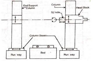
Floor type horizontal boring machine

The floor type horizontal boring machine having no table uses a stationary floor-plate on which T-slots are provided to hold the work.

The headstock supporting column and the end supporting column are mounted on the runways which are placed at right angles to the spindle axis.

Any crosswise adjustment or cross-feed movement is provided by the spindle itself and not by the work.


Floor type horizontal boring machine


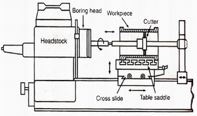
Table type horizontal boring machine

This is the most common type of all horizontal boring machines because the work is mounted on the table which is adjustable and feed is given by hand or power lengthwise or crosswise with respect to the bed of the machine.

The head stock may be adjusted vertically on the column and the spindle has a horizontal feed motion.

The machine consists of bed, head stock supporting column, end supporting column, head stock, saddle and table and boring bar.

This type of machine is suitable for general purpose work where other operations in addition to boring are required to be performed.
 

Horizontal boring machine

In a horizontal boring machine, the work is supported on a table which is stationary and the tool revolves in a horizontal axis.
A horizontal boring machine can perform boring, reaming, turning, threading, facing, milling, grooving and many other operations with suitable tools.
Different types of horizontal boring machines have been designed to suit different purposes.

Horizontal boring machine

Parts of Horizontal boring machine :

Bed :
The bed is fitted on the floor of the shop and has a box-like casting.
The bed supports the columns, tables and other parts of the machine.

Headstock supporting column :
The column provides supports to the headstock and guides it up and down accurately by the guideways provided on the face of the column.

End supporting column :
The end supporting column situated at the other end of the bed houses the bearing block for supporting a long boring bar.

Headstock :
The headstock mounted on the column supports, drives, and feed the tool.
The headstock may be moved up and down on the column for setting the tool for different heights of the work.

Saddle and table :
The table supports the work and provided with T-slots for clamping the work or for holding devices.
The saddle allows the work to be moved longitudinally on the bed.
The table may be moved crosswise on the saddle.

Boring bars :
The boring bar supports the cutter for boring operations on jobs having large bore diameters. 

Size of horizontal boring machine :

The size of that is specified by the diameter of its spindle in mm.
Spindle diameter varies from 75 to 355 mm.
Other important dimensions such as spindle motor horsepower, column heights, size of the table or size of the floor plate, spindle speed, feed and length of feeds, floor space required, the weight of the machine should be stated.

Boring machine mechanism :

The boring machine has different controls for movements of the different parts of the machine. A table type machine has movements mentioned below :
  1. The headstock and the end supporting block may be moved up and down.
  2. The spindle may be rotated with different speeds.
  3. The spindle may be moved in or out by hand or power for feeding.
  4. The saddle or table may be moved by hand pr power.
  5. The columns may be moved by hand or power.

As all the controls are housed in a particular position of the machine the operator may give closed attention on the work while controlling the machine.

Work holding device for horizontal boring machine :

  • Conventional work holding devices comprise of T-bolts and clamps, angle plates, step blocks etc.
  • Special jigs are used in mass production work.
Horizontal boring machine operations :

In boring machine used for milling operation and the milling cutter may be fitted to the spindle. 
Facing cutter is used for machining flat vertical surfaces for face milling operation.
End mills are used to produce grooves and slots.
Other operations such as following below :
  • Drilling 
  • Reaming
  • Counter boring
  • Tapping
  • Spot facing
Boring tool mountings for horizontal boring machine :

The different equipment for mounting cutters in horizontal boring machine are :
  • Boring bar
  • Boring head or cutter head
  • Facing head

There are different boring tool used in boring bars are of different shapes and sizes for different types of operation.

Types of Boring Machine

The boring machine may be classified into four types. we can check it our below :


2. Vertical boring machine
  • Vertical turret lathe
  • Standard vertical boring machine
3. Precision boring machine

4. Jig boring machine
  • Vertical milling machine type
  • Planer type

Boring machine introduction

The first boring machine tool was invented by John Wilkinson in 1775.

The boring machine is one of the most versatile machine tools used to bore holes in large and heavy parts such as engine frames, steam engine cylinders, machine housings etc which are practically impossible to hold and rotate in an engine lathe or a drilling machine.

By the use of the boring machine the range of speeds and feeds provided to various traversing components allow drilling, milling and facing operation with equal facility.

By the fitting of simple attachments, the use of the machine can be extended to include screw cutting, turning, planetary grinding or gear cutting.

What is polorization

Light is electromagnetic in nature. The light is transverse in nature. 

The vibration of the electric field and magnetic field are perpendicular to each other and they are also perpendicular to the direction of propagation of light.

The light in which electric field has the freedom to vibrate in all direction which is perpendicular to the propagation of light is known as unpolarised light.

Unpolorised means it has the freedom and it does not have any restrictions.

The light in which the electric field can vibrate only in one direction in another word there is restriction of vibration of an electric field such light is known as polarised light.
The phenomenon in which unpolarised light is converted into polarized light is known as polarization.

There are different method unpolarised light converted into polarised light :

  • Using polarising materials.
  • By reflection of light.
  • By scattering of light. 
  • By doable refraction of light.

What is diffraction

Diffraction :

Diffraction is the bonding of light around an edge of the obstacle such as the edge of the slit we can diffraction of light through the crack between two fingers at the distant source.

Diffraction of any kind of waves depends upon the wavelength and the size of the obstacle. 

For significant diffraction, the ratio of λ/d should be 1. 

There are two types of diffraction :

  1. Fresnel diffraction
  2. Fraunhofer diffraction

Optical wavelength

What is Optical Wavelength?

When there is a medium which has refractive index µ we have to use optical wavelength λµ.

The relation between optical wavelength and geometrical wavelength is given by 

λµ = λ / µ 

λµ = Optical wavelength

λ = Geometrical wavelength

µ = Refractive index of medium

Electromagnetic spectrum definition

The electromagnetic waves can be characterised by the parameters like wavelength, frequency, phase and state of polarization.


Electromagnetic spectrum


Wavelength :
The distance between two-crust or two throughs is known as wavelength. 
Wavelength denoted by λ.

Frequency : 

Frequency is the quantity that represents a number of oscillations that particle carries out in unit time.
Frequency denoted by ν.

Wavelength (λ) = c / Frequency (ν)

Where c = velocity of electromagnetic wave


Wavelength × Frequency = Velocity of the wave

The wavelength of the electromagnetic wave varies from 10-12 meters to 104 meters.

Phase :
The electromagnetic wave can be represented by a sine or cosine function.

E = E0 Sin (wt + Φ )
Where E = Position of a wave at time t
E0 = Maximum displacement of Amplitude
(wt + Φ ) = Phase of the wave
Φ = Initial phase or phase difference

Phase difference :
The difference between the phase if the two waves or phase of two position of a single wave is known as phase difference.

Wave optics Introduction

In a one-word optics can define that science of light.
Light has dual nature sometimes it behaves like a wave and sometimes it behaves like a particle.
In other word deal with optics is the branch of physics dealing with the study of optical phenomena.
The phenomena like reflection and refraction are explained by corpuscular theory. but the phenomena like interference, diffraction and polarisation can not explain the particle nature of light.
In optics, we consider the light as a wave.

We have also seen terms in optics are following below :

Coherence definition in physics

Coherence :

If the phase difference between two waves or phase difference between two positions of the single wave remains constant, such waves are known as coherent waves and phenomenon is called coherence.

If the phase difference between two sources changes then sources are known as incoherent. Sunlight, incandescent lamp. tube light etc is an example of the incoherent source.

There are two methods by which we can produce a coherent source :
  • Division of wavefront
  • Division of amplitude
Types of coherence :
  • Temporal coherence
  • Spatial coherence
Measurement of coherence :

The coherence of any source can be measured by the visibility of contrast of the fringe system produced by the source. It is given by 

V = Imax - Imin / Imax + Imin 

Where Imax = Maximum Intensity of bright fringe
Imin = Minimum Intensity of dark fringe